
PRODUCT INSTALLATION & OPERATING GUIDE
GP-Probe DIN L1 – PC Kit
Note – Configuration and Technical Expertise
The GP-Probe PC Kit is delivered preconfigured for operation with OSP and Wi-Fi Client mode, making initial setup and everyday use straightforward.
Advanced configurations or modifications beyond the procedures described in this guide require appropriate technical knowledge and engineering skills. Such changes should only be performed by qualified personnel.
Note – Security
The GP-Probe PC Kit is supplied with default credentials for Web, SSH, and Wi-Fi access. These credentials are publicly documented and therefore should not be considered secure.
We strongly recommend changing all default passwords during the initial setup, especially the SSH root password, to prevent unauthorized access to the system.1. System overview
The GP-Probe DIN L1 PC Kit is a self-contained GNSS interference monitoring and data-logging system housed in an IP66-rated protective case. It combines the GP-Probe DIN L1 signal analyzer with a compact microcomputer and removable SD card.
The GP-Probe measures GNSS signal quality, monitors for interference and anomalies, and delivers measurement packets through its licensed STREAM interface. The microcomputer acts as a local recorder and a network access point or bridge. It stores a continuous binary measurement history on the installed microSD card in both operating modes.
1.1 Two operating modes
Mode | GNSS analysis | Network / GP-Cloud | microSD logging |
A. Standalone / Access Point | Onboard Signal Processing (OSP) on GP-Probe | PC Kit broadcasts its own Wi-Fi; internet and GP-Cloud are not required | Enabled continuously |
B. Connected / | GP-Cloud data processing | PC Kit joins an existing Wi-Fi network; the microcomputer passes probe traffic to GP-Cloud | Enabled continuously |
The two settings are independent: Wi-Fi mode determines the network connection, while “Data Processing” in the GP-Probe configuration determines where interference analysis runs. STREAM and microSD recording remain active in both intended configurations.
1.2 Data paths
Standalone: GNSS antenna → GP-Probe DIN L1 (OSP detection + STREAM) → integrated microcomputer → microSD. A laptop or phone connects directly to the GP-ProbeWiFi access point to monitor the system and download files.
Connected: GNSS antenna → GP-Probe DIN L1 (STREAM + GP-Cloud mode) → integrated microcomputer → (a) microSD recording and (b) existing Wi-Fi network → GP-Cloud. Local access is available over the same Wi-Fi network.
2. Package contents and prerequisites
Included with the PC Kit | Function |
IP66-rated protective case | Encloses and protects the assembled system |
GP-Probe DIN L1 — PPS / BL / RL / SCR | GNSS RF monitoring; PPS, blocker, relay and display features |
GP-Probe DIN L1 software options: OSP and STREAM | Local interference processing and raw/processed measurement streaming |
Beagle-based compact microcomputer | Integrated web console, Wi-Fi connectivity and local recording |
128 GB microSD card | Local measurement storage |
| Power Bank | USB power bank with a 20,000 mAh capacity (approx. 74 Wh). Compliant with standard airline carry-on baggage limits for lithium-ion batteries (under 100 Wh). |
Wi-Fi antenna | Local access point or existing Wi-Fi network connectivity |
Magnetic GNSS antenna, 3 m cable | Receives GNSS signals for measurement |
3. Default connectivity and accounts
3.1 Current factory defaults
Item | Current value / behavior |
Wi-Fi mode at first use | Access Point |
Wi-Fi network name (SSID) | GP-ProbeWiFi |
Wi-Fi password | iwYoN@P6hd |
Microcomputer control panel (AP / wired local interface) | http://192.168.0.100 |
Web administrator | admin / admin — change required on first sign-in |
Web operator account | user / user — restricted access; administrator manages its password |
Microcomputer SSH (authorized technical service only) | root / fFoxB@t_l)6f#nnFZ7Ps |
GP-Probe web interface | Open from “Probe connection”; the probe IP is configured separately (default GP-Probe IP: 192.168.0.120) |
3.2 Connect for the first time
1. Connect the magnetic GNSS antenna to the GNSS input, place it with a broad view of the sky, and power the kit using its power input.
2. On your laptop or phone, select Wi-Fi network “GP-ProbeWiFi” and enter the default Wi-Fi password.
3. Open http://192.168.0.100 in a browser (HTTP, not HTTPS). Sign in as admin with the initial password admin.
4. When prompted, assign a new administrator password (8–128 characters) and save it. The management panel becomes available after this step.
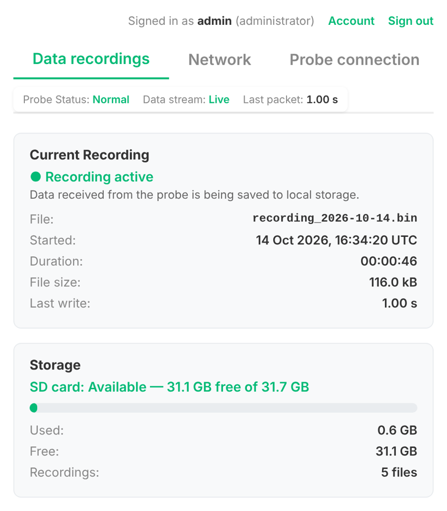
5. Check the Data recordings tab for the GNSS status, stream status, active recording and SD-card capacity.
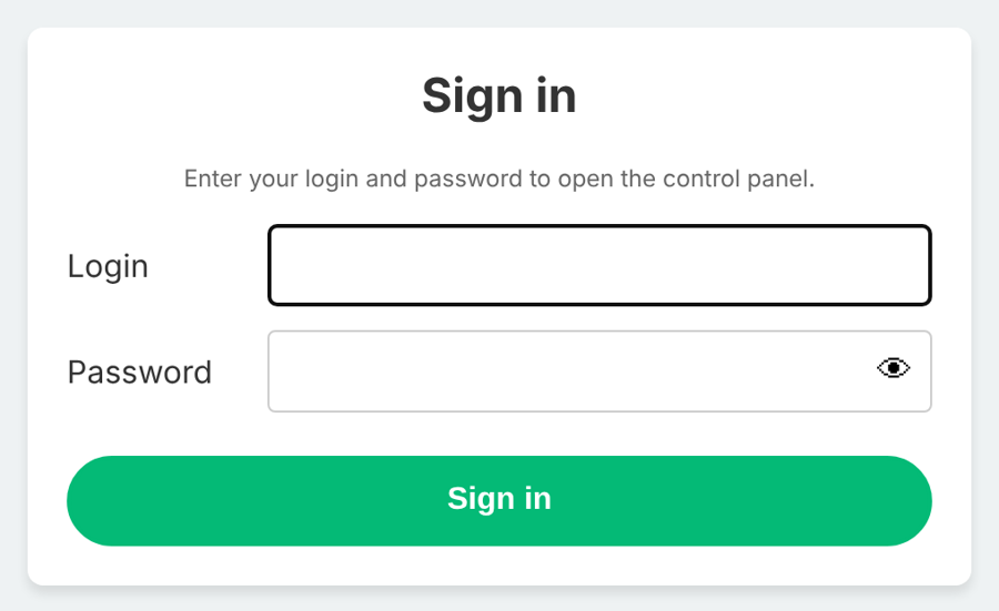
Figure 1. The microcomputer sign-in form. Enter admin/admin at the initial login.
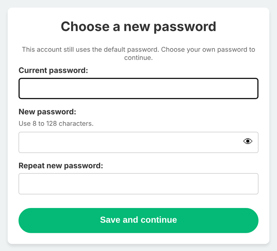
Figure 2. The first-login password change screen; configure a new administrator password to continue.
3.3 Connect by Ethernet
The controller can also be reached through its wired LAN connection. Connect a computer to the LAN port of the case. In the default local subnet, assign the computer an unused address such as 192.168.0.10 with subnet mask 255.255.255.0 (if the computer does not already obtain a suitable address), then open http://192.168.0.100.
This wired route is particularly important if Client mode was selected with incorrect Wi-Fi credentials and the “GP-ProbeWiFi” access point is no longer broadcast. Restore the network configuration from the Network tab after logging in via LAN.
4. Microcomputer web console
The console contains three tabs. A common status strip reports Probe Status, Data stream and Last packet. The administrator can manage network and probe connectivity; the user role can read status and download recordings.
Console tab | Purpose | Access |
Data recordings | Recording health, card capacity, recorded .bin files; download and authorized deletion | admin and user |
Network | Select Access Point or Wi-Fi Client; configure Wi-Fi and IP settings | admin only |
Probe connection | Set the GNSS probe IP, set the forwarded web port and open its interface | admin only |
4.1 Probe connection
The microcomputer communicates with the GP-Probe over the local wired network. Open Probe connection and check Probe IP address. Enter the actual IP configured on the probe, not the microcomputer IP. The default GP-Probe address is normally 192.168.0.120, but the example screenshot uses 192.168.0.153.
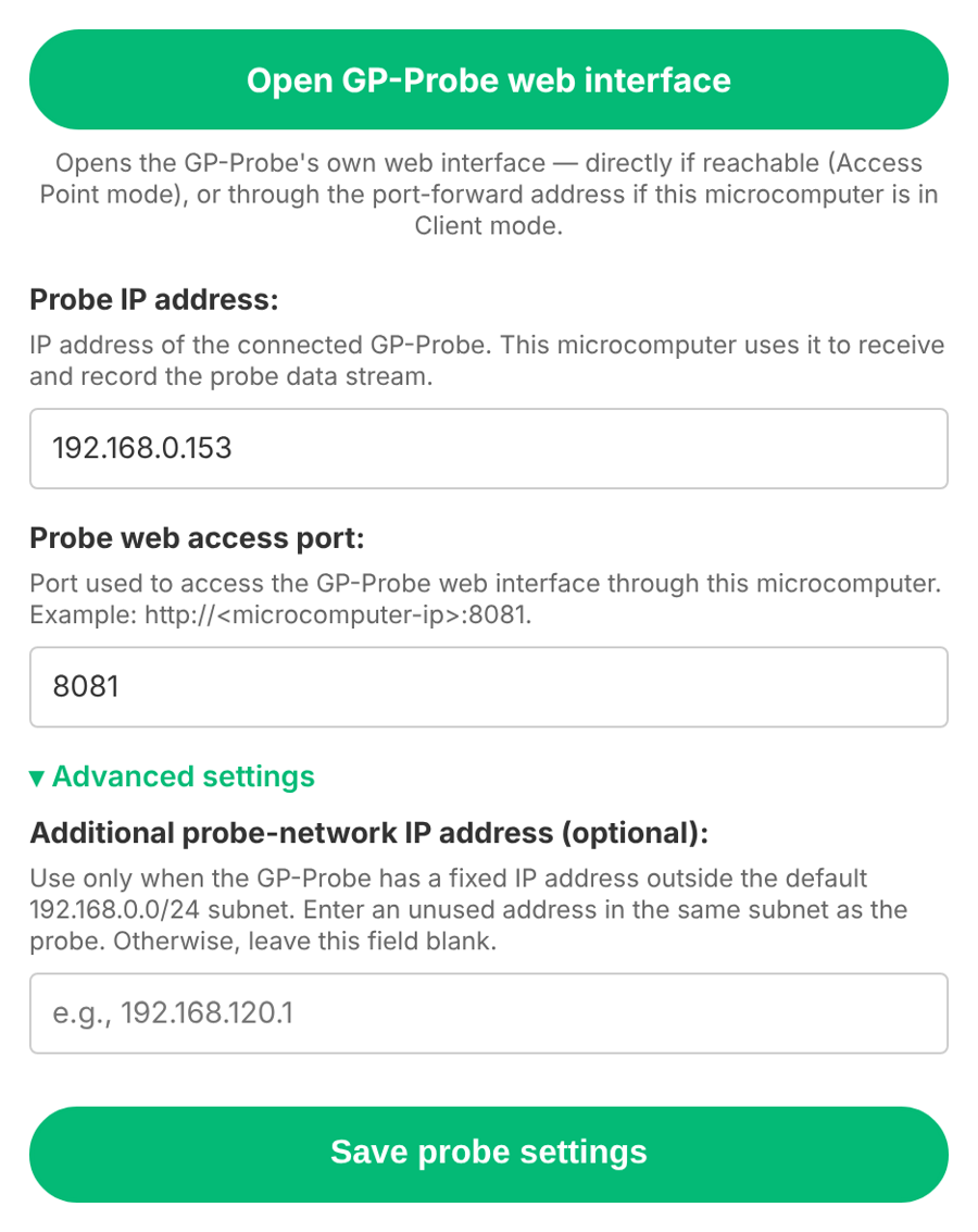
Figure 3. Probe connection: probe IP address, forwarded web access port, and optional second subnet address.
The “Open GP-Probe web interface” button opens the GP-Probe configuration page: directly in Access Point mode, or through the microcomputer’s forwarded address in Wi-Fi Client mode. The example forwarding port is 8081. Do not choose ports 8080, 8083 or 8084 for this forwarding function.
The optional “Additional probe-network IP address” field is intended only when the probe uses an address outside the normal 192.168.0.0/24 subnet. Leave it blank unless a network administrator supplies an appropriate address in the probe’s subnet.
5. Mode A — fully standalone operation
Use this mode when no internet connection is available or when a portable on-site logging station is needed. The probe detects GNSS anomalies locally using its OSP algorithms; the microcomputer records the streamed measurements without any GP-Cloud connection.
5.1 Keep the microcomputer in Access Point mode
1. Open Network in the microcomputer console.
2. Select “Create a local Wi-Fi network” (Access Point mode).
3. Confirm or update the Network name (SSID) and Wi-Fi password. The current default SSID is GP-ProbeWiFi.
4. Click “Save & apply”. The access point restarts and your laptop or phone may disconnect. Reconnect to the new or retained network name.
5. Open http://192.168.0.100 again and confirm “Access point active” in Network status.
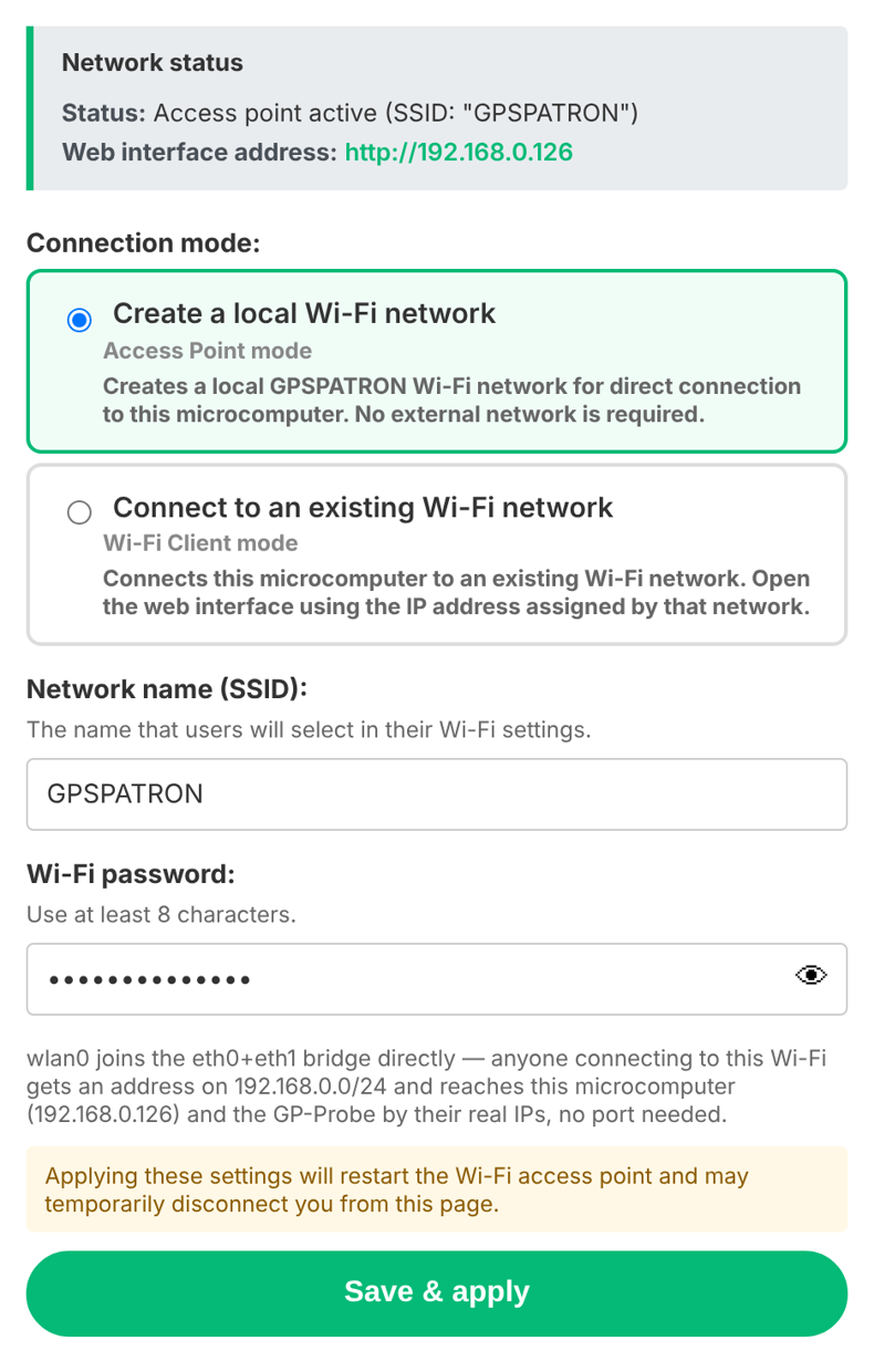
Figure 4. Network tab in Access Point mode; select “Create a local Wi-Fi network” and save settings.
5.2 Enable local detection and STREAM on the GP-Probe
1. Open the GP-Probe web interface from the controller’s Probe connection tab. Sign in with the GP-Probe’s own administrator credentials (these are separate from the microcomputer login).
https://support.gpspatron.com/en/support/solutions/articles/101000495748-quick-start
2. In the GP-Probe Admin / Licenses menu, verify that the OSP and STREAM options are activated.
3. Under Measurement Config, select “Onboard Signal Processing (OSP)” as Data Processing; choose the desired traceable GNSS constellations and apply changes.
4. Enable the STREAM option in the GP-Probe configuration. This allows the integrated microcomputer to receive measurements over the probe WebSocket (STREAM service, normally TCP port 8083).
5. For a new antenna location, open Status / Measurements, normalize the power spectrum, collect data for at least five minutes, calibrate the anomaly algorithm and set a reference position. Adjust detection thresholds for the site.
6. Return to the microcomputer Data recordings tab and verify that Data stream is Live and Current Recording shows Recording active.
GP-Probe and microcomputer have different configuration interfaces and accounts. In standalone mode, GP-Cloud is not needed for detection, recording, downloading or CSV conversion.5.3 Confirm that the logger is recording
On Data recordings, “Recording active” indicates that received measurements are being written to microSD. File, Started, Duration, File size and Last write give the current file name and its progress. The Storage block shows available capacity and number of files.
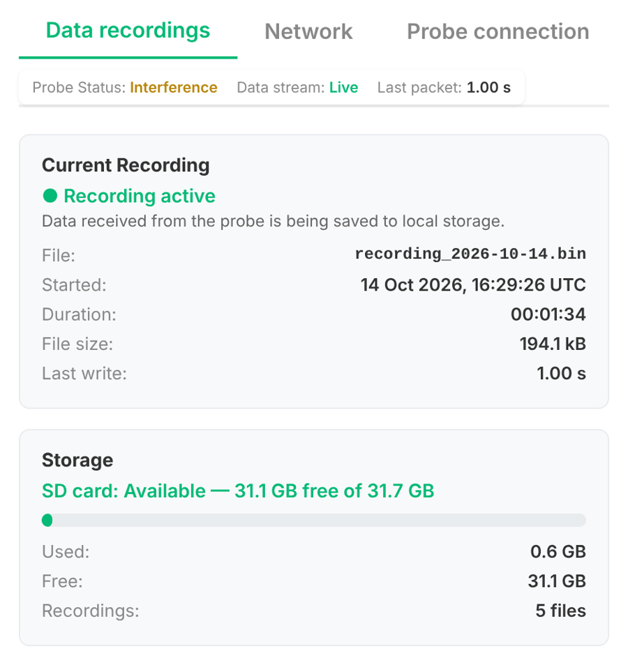
Figure 5. Active recording: a live packet stream, current daily file and microSD capacity.
The display may temporarily show “Waiting for GPS fix” during startup. Until a valid GNSS time is available, measurements can be stored in unknown_date_time.bin; dated files begin after the controller has a reliable time reference.
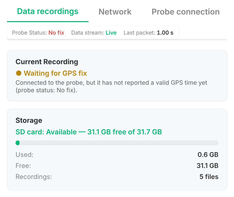
Figure 6. Waiting for GPS fix: the GNSS stream is present, but the controller has not yet set its recording clock.
6. Mode B — connected operation through Wi-Fi Client
Use this mode when the site has an existing Wi-Fi network and you want GP-Probe measurements and detection results in GP-Cloud. The microcomputer provides Wi-Fi connectivity to the probe while continuing to store its STREAM measurements to the microSD card.
6.1 Join an existing Wi-Fi network
1. While still connected to GP-ProbeWiFi (or by Ethernet), sign in as admin and open Network.
2. Select “Connect to an existing Wi-Fi network” (Wi-Fi Client mode).
3. Enter the Wi-Fi network name and password, and select Automatic (DHCP). Use Manual (static IP) only if the network administrator provided the IP, subnet mask and gateway.
4. Ensure the external Wi-Fi network is not within 192.168.0.0/24. This subnet is reserved for the local probe/controller side; overlapping addresses prevent switching or routing correctly.
5. Click “Save & connect”. The GP-ProbeWiFi access point disappears. The control-panel URL changes to the Wi-Fi IP assigned to the microcomputer.
6. From a device on the same Wi-Fi network, open http://<controller-Wi-Fi-IP>. You can find this IP on the Network status display or in the Wi-Fi router’s client/DHCP list. Wired recovery remains available via 192.168.0.100.
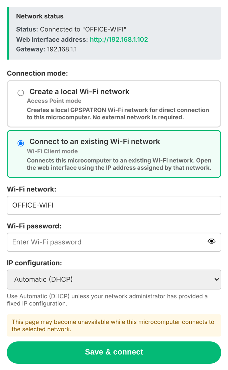
Figure 7. Wi-Fi Client configuration with Automatic (DHCP); the connected network assigns the controller IP.
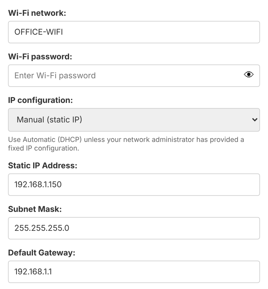
Figure 8. Optional manual/static address fields for networks requiring a fixed Wi-Fi IP.
If Wi-Fi credentials or DHCP fail, the device may retain Client mode without obtaining a Wi-Fi address, so its Access Point will no longer be visible. Connect through Ethernet and restore Network settings. Avoid external Wi-Fi subnets overlapping 192.168.0.0/24.6.2 Connect the GP-Probe to GP-Cloud
1. Confirm the Wi-Fi network has internet access. In GP-Cloud, register the GP-Probe using its unique Probe ID and create its API password (a valid GP-Cloud license/subscription is required).
2. In the microcomputer Probe connection tab, check the probe IP and click “Open GP-Probe web interface”. In Client mode the page is available via a forwarded port such as http://<controller-Wi-Fi-IP>:8081.
3. In the GP-Probe Connection Config menu, enter the GP-Cloud server address (typically gp-cloud.io for the hosted service) and the API password created during registration.
4. In GP-Probe Measurement Config, select “GP-Cloud” for Data Processing and apply. Keep STREAM enabled so that the microcomputer continues saving measurement data locally.
5. In GP-Cloud, verify that the probe is online, measurement charts are updating and cloud-side calibration/thresholds are configured for the current installation.
6. In the microcomputer Data recordings tab, verify both Data stream: Live and Current Recording: Recording active. The microSD recorder continues working in Client mode even while cloud connectivity is used.
6.3 What the controller records in Client mode
The latest PC Kit firmware does not stop writing to microSD when switching to Wi-Fi Client. A temporary GP-Cloud outage does not by itself mean that recording must stop, as long as the controller continues receiving the GP-Probe STREAM data and its SD card is available. Recordings are retrieved through the same Data recordings page used in standalone mode.
7. Working with recordings and the SD card
7.1 Files, timestamps and capacity
The controller saves the incoming binary STREAM packets as daily .bin files. After GNSS time is established, a file named recording_YYYY-MM-DD.bin is used for each UTC day; a new dated file begins at 00:00 UTC. Data received before a valid time is available may be placed in unknown_date_time.bin.
The reference implementation receives approximately one 2,521-byte measurement record per second, which is roughly 218 MB per day. Actual retention depends on recorded payloads, filesystem overhead, usage and available card capacity. Check the free-space indicator; do not rely on a fixed number of months or an undocumented automatic overwrite policy.
7.2 Download and delete recordings
1. Open Data recordings. The Storage section shows card availability, used/free space and number of files.
2. Locate a dated .bin recording or unknown_date_time.bin. Click Download to save a copy to your computer. Both admin and user can download.
3. Only admin may use Delete. Confirm the operation carefully, especially for the current daily file; an active recorder may recreate that file if it is deleted.
4. Click Refresh list to discover newly created files. The list also refreshes when the page/tab is opened or after a deletion.
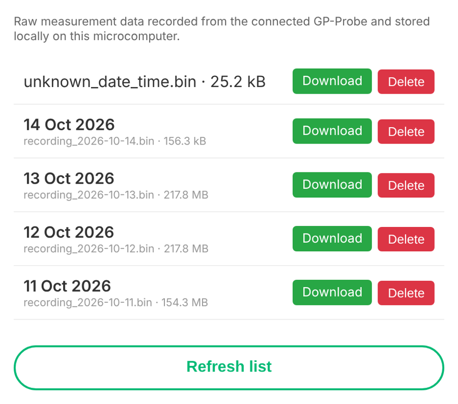
Figure 9. Recorded files with UTC dates, file sizes, Download/Delete controls and Refresh list.
7.3 SD-card errors and missing data
The recorder requires an accessible microSD card for storing its measurements. If the card is missing, full, read-only or has an I/O error, the web console reports a storage problem. In the reference firmware, card access is retried approximately every five seconds. Check the card rather than assuming that a healthy live stream means data has been saved.
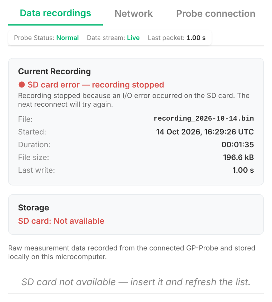
Figure 10. Recorder not running with SD card not available. Check whether the card is inserted and accessible.
8. Convert recorded BIN files to CSV
The PC Kit writes binary GP-Probe STREAM data. For offline analysis, download a .bin file and use the official GPSPATRON parser to convert it to CSV. The parsed CSV can be opened in Excel or imported into analysis software; it includes device status, GNSS signal quality, satellite measurements, interference metrics, spectrum data and position-related diagnostics.
8.1 Conversion procedure
1. Download the required recording_YYYY-MM-DD.bin (or unknown_date_time.bin) from Data recordings onto your computer.
2. Open the GPSPATRON support article “How to Enable Raw Data Streaming on GP-Probe DIN L1”, then download the attached Python parser GP_Probe_DIN_L1_Parser_v.2.py. Use the current attachment, rather than older v1.1 examples.
3. Install Python 3.8 or newer if necessary. Place the parser and the downloaded binary file in a convenient working folder.
4. Open a terminal in that folder and start the parser using the command below. When prompted by the script, select or enter the path to the downloaded .bin file.
5. Locate the generated .csv file, normally next to the input file, and open it in a CSV-compatible application. Preserve the original .bin file for future reprocessing.
python GP_Probe_DIN_L1_Parser_v.2.py
The parser’s source article also includes a Python WebSocket receiver and sample BIN/CSV files. No extra WebSocket receiver is required for PC Kit logging because the integrated microcomputer already records the probe stream.
Official download and parser instructions: How to Enable Raw Data Streaming on GP-Probe DIN L1
9. Reading system status and diagnosing problems
9.1 Status strip
Indicator | How to interpret it |
Probe Status | Status reported by the probe: Normal, Interference, Anomaly, No fix, PPS Offset, Low position accuracy, Hardware error, etc.; Disconnected if there is no probe connection. |
Data stream | Live: a recent packet (typically <5 s). Stalled: packets have not arrived recently. Waiting: none received yet. No data: recorder not connected. |
Last packet | Time since the latest packet; normally around 1 second for an active stream. This is a freshness measurement, not a signal-quality score. |
Current Recording | Confirms whether data is actually being written, independent of whether the probe’s interference status is Normal. |
9.2 Troubleshooting checklist
Symptom | Checks / action |
GP-ProbeWiFi cannot be found | Controller may be in Client mode. Try wired Ethernet at http://192.168.0.100; verify power. |
Cannot open http://192.168.0.100 | Verify you are on GP-ProbeWiFi or the wired 192.168.0.0/24 network. In Client mode use the Wi-Fi-assigned IP. |
GP-Probe web interface does not open | Verify actual Probe IP address and forwarded port in Probe connection; test direct probe address in AP mode. |
Not connected / No data | Check probe power, Ethernet connection, enabled STREAM option and network reachability. |
Data stream: Stalled | Check if latest packet interval increases, probe streaming settings, GNSS probe state and link stability. |
Waiting for GPS fix / unknown_date_time.bin | Check the antenna, sky view, acquisition state and GNSS time. Allow the probe to acquire a valid fix. |
SD card not available / error | Check seating, free space, card health and read-only errors; replace defective media. Confirm the active recording resumes. |
GP-Cloud reports Offline in Client mode | Confirm existing Wi-Fi has working internet, correct GP-Cloud URL/API password, probe registration and GP-Cloud data processing mode. |
Wi-Fi Client connection failed | Check SSID/password, DHCP, gateway and subnet conflicts. Use wired access to recover settings. |
False GNSS anomalies | Install antenna with an open sky view and away from RF noise/multipath; normalize spectrum and recalibrate OSP or GP-Cloud detector. |
10. Access control and operational security
10.1 Web administrator and user roles
Function | admin | user |
View Probe Status, stream and storage | Yes | Yes |
List and download recordings | Yes | Yes |
Delete recordings | Yes | No |
Configure Network or Probe connection | Yes | No |
Manage operator credentials | Yes | No |
Change own password through Account | Yes | Yes |
10.2 SSH access (technical service only)
The controller provides SSH access for authorized maintenance. Its default root credentials are listed in Section 3.1 solely for provisioning/service reference. Change the root password before attaching the controller to a shared or untrusted network. Normal PC Kit operation, data downloads and mode switching are completed through the web console and do not require SSH.
Note – Security Recommendation
This document is publicly available, and all default login credentials, including SSH access credentials, are publicly disclosed. For security reasons, we strongly recommend changing all default passwords immediately after the initial setup, especially the SSH root password, to prevent unauthorized access to your device.
11. Related GPSPATRON technical articles
GP-Probe DIN L1 — Quick Start • How to Enable Raw Data Streaming on GP-Probe DIN L1 • How to Get Access to Configuration Panel • DIN L1 — Anomaly Detection High False-Positive Rate • GP-Probe registration in GP-Cloud • How does the GP-Probe connect to the Internet?