
Overview
The GP-Blocker is a GNSS protection device designed to safeguard time servers and GNSS receivers against spoofing attacks. It combines a high-isolation RF switch (110 dB) with an embedded L-band GNSS jammer to prevent counterfeit satellite signals from reaching protected equipment.
The GP-Blocker is installed between the GNSS antenna and the protected receiver. When a spoofing attack or other critical GNSS signal anomaly is detected by the GP-Probe TGE2 monitoring system, the GP-Blocker can automatically disconnect the GNSS signal path.
As a result, the protected time server loses GNSS reception and switches to Holdover mode, relying on its internal oscillator to maintain accurate time synchronization instead of following potentially manipulated satellite signals. For other GNSS receivers, the response depends on their capabilities and configuration.
General Connection Diagram
The diagram below illustrates a typical GP-Blocker installation with a GP-Probe TGE2, a protected time server, and GP-Cloud.
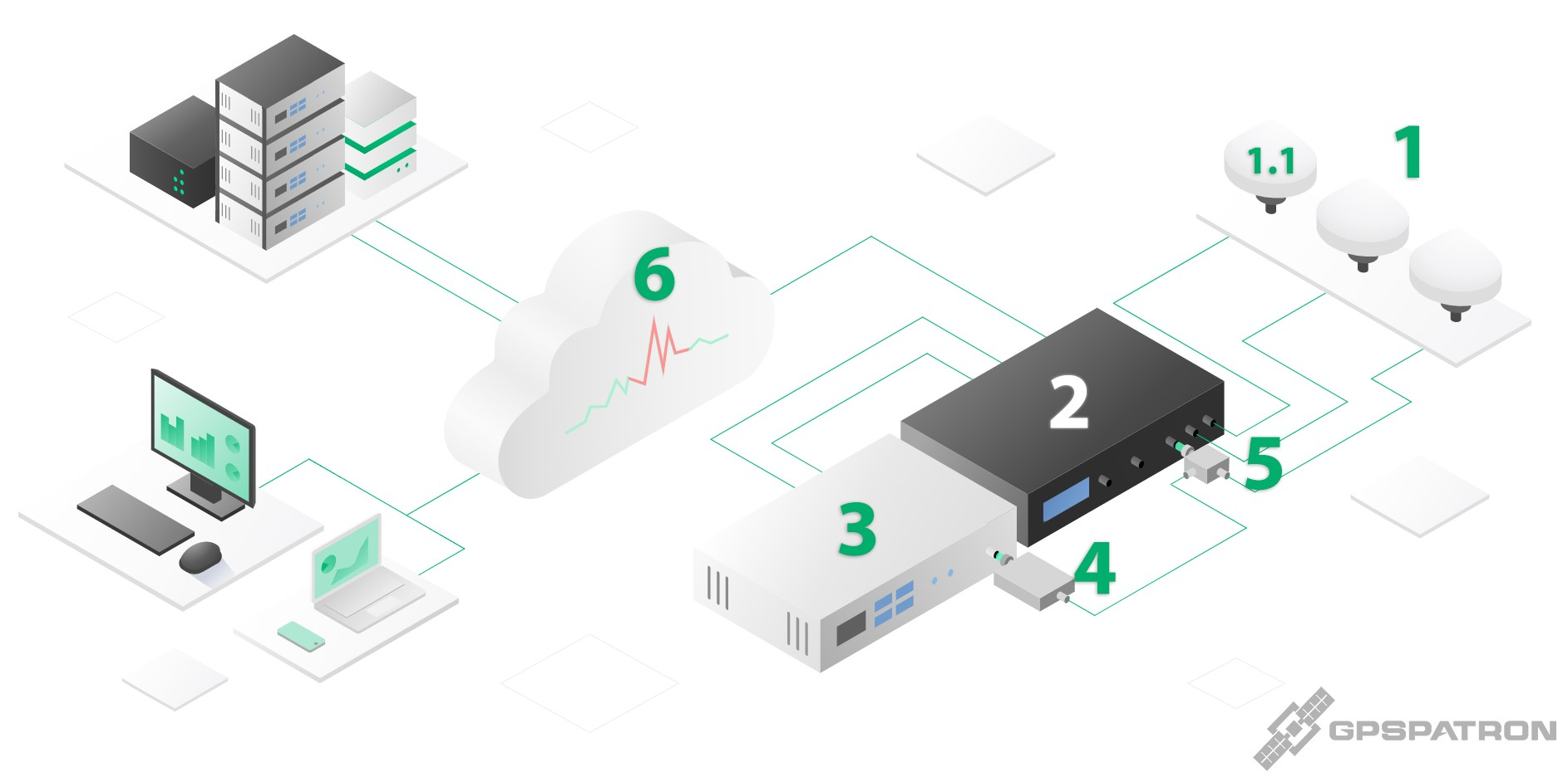
Figure 1. General connection diagram of GP-Blocker with GP-Probe TGE2 for GNSS spoofing protection.
1. GNSS Antenna System
The GP-Probe TGE2 uses three spatially separated GNSS antennas to monitor satellite signals and detect sophisticated spoofing attacks through spatial signal analysis.
1.1. Shared GNSS Antenna
The first antenna is shared between the GP-Probe TGE2 and the protected time server using a GP-Divider. This allows both devices to receive signals from the same GNSS antenna.
2. GP-Probe TGE2
The GNSS interference detector continuously monitors satellite signals, detects anomalies, and provides real-time data to GP-Cloud. Its first GNSS channel is connected to the shared antenna through the GP-Divider.
3. Protected Time Server / GNSS Receiver
The equipment being protected against GNSS spoofing. Its GNSS antenna input is connected to the shared antenna through the GP-Blocker and GP-Divider.
4. GP-Blocker
The GNSS protection device installed in the RF signal path between the antenna and the protected receiver. Upon receiving a blocking command from the GP-Probe TGE2 via M8 BUS RS-485, it disconnects the GNSS signal path to prevent spoofed signals from reaching the receiver.
5. GP-Divider
A two-way GNSS signal splitter that allows the GP-Probe TGE2 and the protected time server to share a single GNSS antenna.
6. GP-Cloud
The cloud-based GNSS monitoring and processing platform. It analyzes data received from the GP-Probe TGE2, detects interference and spoofing events, and sends event notifications to the probe.
How the Protection Works
During normal operation, the GP-Blocker allows GNSS signals to passthrough to the protected receiver. When GP-Cloud detects a spoofing attack, interference, or significant GNSS signal degradation, it notifies the GP-Probe TGE2. The probe then sends a control command to the GP-Blocker over the proprietary M8 BUS RS-485 interface. The GP-Blocker disconnects the protected receiver from the GNSS antenna, preventing counterfeit signals from affecting its operation. A time server with Holdover capability switches to its internal oscillator, preserving synchronization until reliable GNSS reception can be restored.
The GP-Probe TGE2 continues monitoring GNSS signals independently, allowing the system to determine when normal reception conditions have returned.
Physical Connection Options
The GP-Blocker package includes the following hardware:
- 1 × GP-Blocker
- 2 × M8 BUS cables
- 2 × GP-Blocker Bus Interface Adapters
These accessories allow the GP-Blocker to be connected to the GP-Probe TGE2 in several different ways, depending on the installation scenario.
Connection Principles
In the simplest case, a GP-Blocker can be connected directly to the GP-Probe TGE2 using the proprietary M8 BUS cable. This is the most convenient solution when only one time server must be protected and the protected equipment is installed close to the probe.
For more flexible installations, the GP-Blocker Bus Interface Adapter is used. The adapter converts the proprietary M8 BUS interface into an RS-485 bus over a standard RJ45 twisted-pair cable. This makes it possible to install blockers much farther away from the probe and to connect multiple GP-Blockers to the same shared bus.
Important: although a standard RJ45 twisted-pair cable is used, this is not an Ethernet connection. The cable carries RS-485 communication only.
A single GP-Probe TGE2 can control up to four GP-Blockers connected on the same RS-485 bus.
Connection Scenarios
1. Direct Connection to a Nearby Time Server
This is the simplest protection scenario.
Use this option when:
- only one time server or GNSS receiver needs protection;
- the protected device is installed close to the GP-Probe TGE2;
- no distributed bus layout is required.
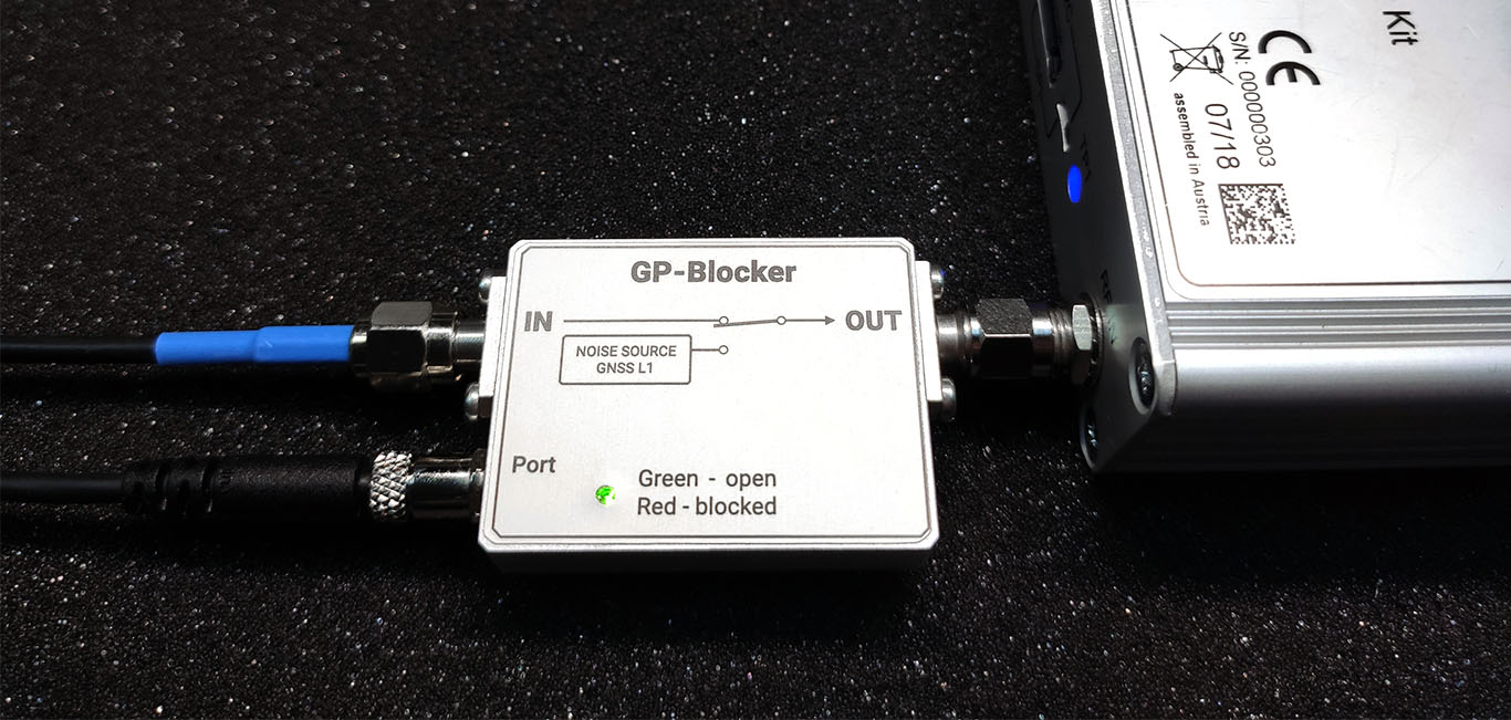
In this configuration:
- the GP-Blocker is installed directly on the GNSS antenna input of the protected time server or GNSS receiver;
- the blocker is connected directly to the GP-Probe TGE2 with a proprietary M8 BUS cable.
This is the recommended option for compact installations where the protected equipment is located only a short distance from the probe.
2. Remote Connection to One Distant Time Server
Use this option when the protected time server is located far from the GP-Probe TGE2.
In this configuration:
- one GP-Blocker Bus Interface Adapter is installed near the GP-Probe TGE2;
- the second GP-Blocker Bus Interface Adapter is installed near the GP-Blocker;
- the two adapters are connected with a long RJ45 twisted-pair cable carrying the RS-485 bus;
- the GP-Blocker is connected to the remote adapter using the proprietary M8 BUS cable.
Since the RJ45 bus cable carries data only, the remote GP-Blocker must be powered locally. This can be done:
- via USB, or
- via a local 12 VDC power source, depending on the installation method.
This option is ideal when the probe and the protected time server cannot be installed close to each other.
Example of Remote Bus Connection:
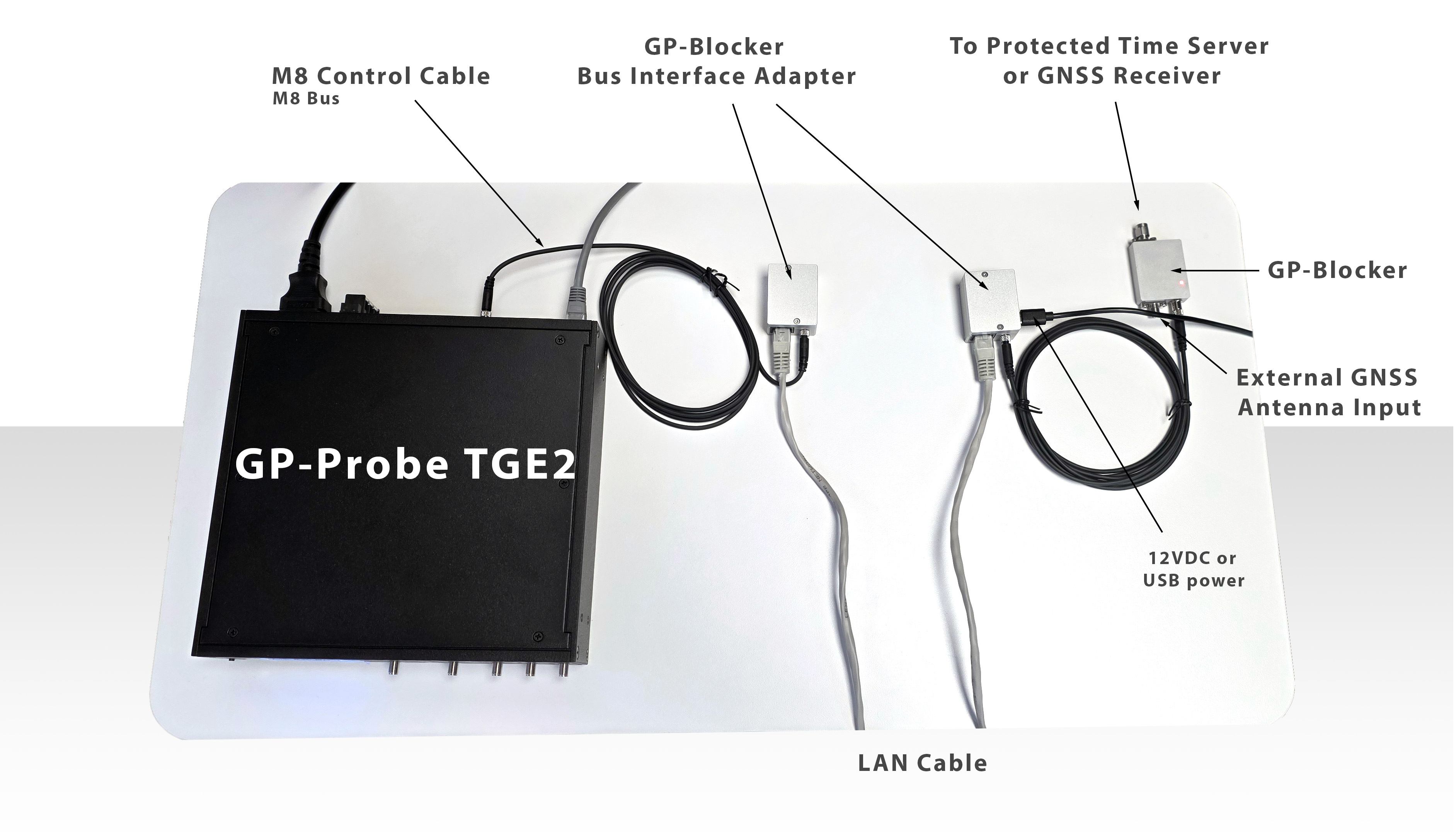
The photo below shows an example of a single GP-Blocker connected to a GP-Probe TGE2 through two GP-Blocker Bus Interface Adapters and a long RS-485 bus cable.
In this example:
- the first adapter is connected to the GP-Probe TGE2;
- the second adapter is connected to the GP-Blocker;
- the long RJ45 twisted-pair cable between them carries the RS-485 bus;
- the remote blocker can be installed close to the protected time server.
3. Shared RS-485 Bus with Multiple GP-Blockers
For larger installations, multiple GP-Blockers can be connected to the same shared RS-485 bus.
In this configuration:
- the GP-Blocker Bus Interface Adapters are used to build a distributed RS-485 network;
- multiple blockers can be installed at different physical locations;
- up to four GP-Blockers can be connected to one GP-Probe TGE2.
This architecture is useful when:
- several time servers must be protected by a single probe;
- blockers must be installed close to different protected receivers;
- long cable runs are required.
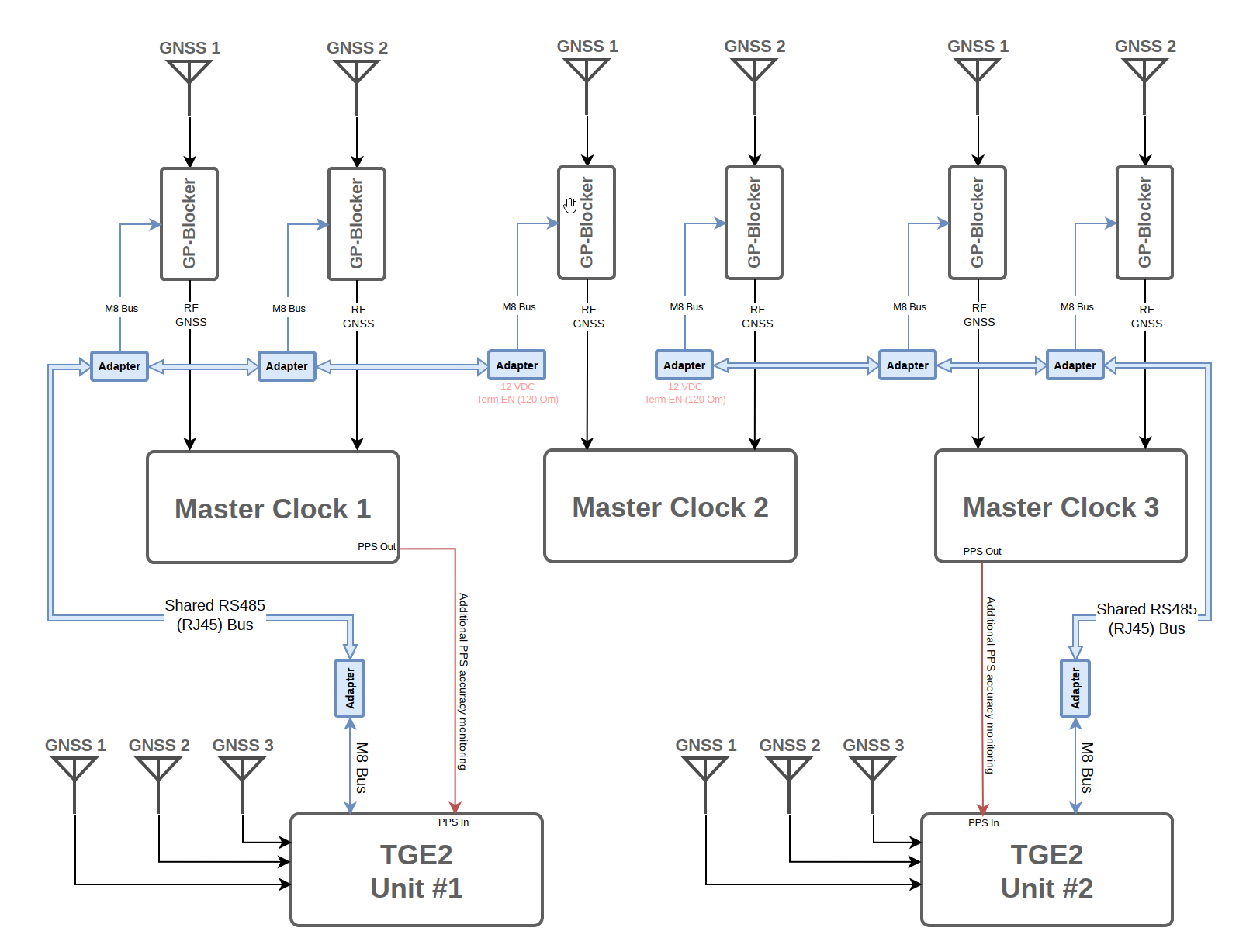
Because the bus operates at a low communication speed (9600 baud), long RS-485 cable runs are possible. In practice, this makes the solution suitable for large sites and distributed installations.
Why Use the GP-Blocker Bus Interface Adapter?
The GP-Blocker Bus Interface Adapter serves two main purposes:
- Distance extension
It allows the GP-Blocker to be installed far from the probe by replacing the short proprietary connection with a long RS-485 twisted-pair cable. - Bus sharing
It allows multiple GP-Blockers to share the same communication bus, so one GP-Probe TGE2 can control several blockers at once.
This makes the system much more flexible for real-world deployments, especially in telecom, timing, and critical infrastructure installations.
GP-Blocker Configuration in GP-Probe TGE2
To configure the GP-Blocker, open the GP-Probe TGE2 Embedded Web Panel and navigate to the GP-Blocker section. Here you can specify the blocker's RS-485 address, enable automatic protection, configure its behavior when GP-Cloud is unavailable, adjust the embedded jammer settings, and manually test the RF switch using the Open and Close buttons.
For detailed configuration instructions, see How to Configure GP-Blocker on GP-Probe TGE2.