
The GP-Probe TGE2 supports remote control of up to four GP-Blockers through a shared proprietary M8 BUS RS-485 interface. Each blocker can be configured individually, allowing different protection rules for multiple GNSS receivers or time servers.
All GP-Blocker settings are managed through the GP-Probe TGE2 Embedded Web Panel.
1. Access GP-Blocker Configuration
- Open the GP-Probe TGE2 Embedded Web Panel in your browser.
- Navigate to the GP-Blocker section.
- Configure the GP-Blocker address and protection settings as described below.
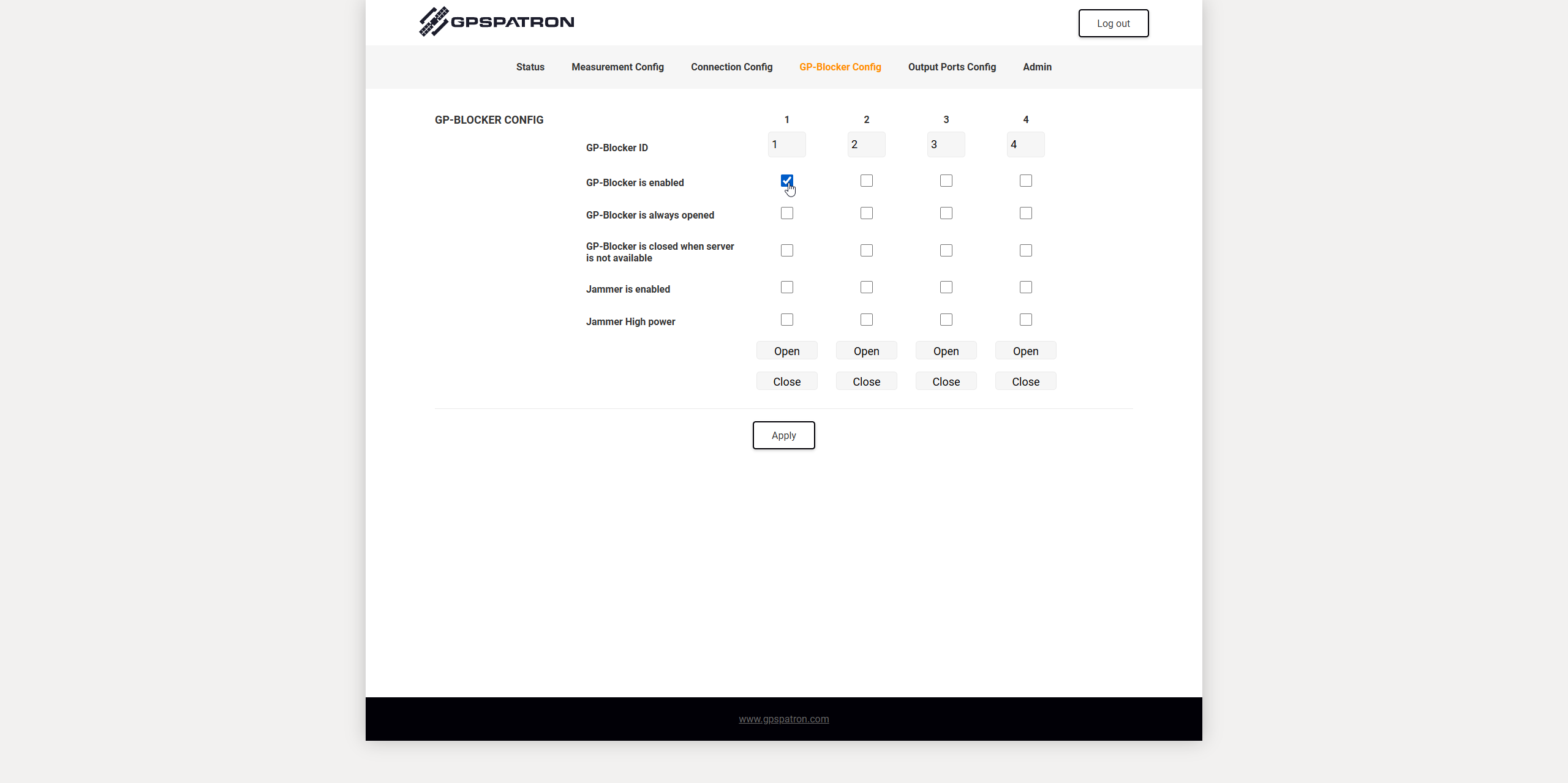
2. GP-Blocker Address Configuration
Each GP-Blocker has a configurable RS-485 device address. By default, all GP-Blockers are shipped with address 1.
If you are connecting only one GP-Blocker, you can leave the default address unchanged.
If multiple GP-Blockers are connected to the same RS-485 bus, each must have a unique address to allow individual control and configuration.
To change the GP-Blocker address:
- Connect the GP-Blocker to your computer using a GP-Blocker Bus Interface Adapter equipped with a USB Type-C port.
- Open any serial terminal application and connect to the adapter's virtual COM port.
- Use the GP-Blocker API assign a new device address.
- Repeat the procedure for each additional GP-Blocker.
The serial interface operates at 9600 baud. The API commands and communication protocol are documented in the GP-Blocker Datasheet.
Note: Although the GP-Blocker addressing scheme supports multiple device IDs, a single GP-Probe TGE2 supports a maximum of four connected GP-Blockers.
3. GP-Blocker Settings
The following settings are available in the GP-Blocker configuration section.
GP-Blocker Address
Specifies the RS-485 address of the GP-Blocker to be configured and controlled.
GP-Blocker Enabled
Enables control of the selected GP-Blocker. This option must be checked for the probe to manage the blocker.
GP-Blocker Is Always Open
Keeps the GP-Blocker RF channel open regardless of the current detection status. GNSS signals continue passing through to the protected receiver.
This option effectively disables automatic GNSS blocking for the selected device.
GP-Blocker Is Closed When Server Is Unavailable
Automatically closes the GP-Blocker RF channel when the GP-Cloud server becomes unavailable.
This provides additional protection when cloud-based interference detection is temporarily unavailable.
Enable Jammer
Enables the GP-Blocker's embedded GNSS jammer when the RF channel is closed.
By default, the jammer operates in Low Power mode. It provides additional suppression of residual GNSS signals that may leak through the RF switching circuitry.
Jammer High Power
Switches the embedded jammer to High Power mode.
The GP-Blocker provides approximately 110 dB of RF isolation. However, during exceptionally powerful spoofing attacks, such as those encountered in active military conflict zones, this isolation may not be sufficient.
High Power mode provides additional suppression of such strong counterfeit GNSS signals.
For most installations, Low Power mode is recommended.
4. Manual GP-Blocker Testing
The configuration panel provides two buttons for manually testing the GP-Blocker:
- Open — Opens the RF channel, allowing GNSS signals to pass through to the protected receiver.
- Close — Closes the RF channel, blocking GNSS reception on the protected receiver.
These buttons are intended for short functional tests rather than permanent manual control.
Important: When the GP-Probe is connected to GP-Cloud, the automatic protection logic remains active and may immediately override a manual command.
For example, if the GP-Probe status is Normal and you manually click Close, the GP-Blocker may immediately return to the Open state.
This behavior is expected and indicates that the automatic protection logic is controlling the blocker according to the current system status.