
Applies to: GP-Probe DIN L1 and GP-Probe TGE2 with a compatible RF spectrum measurement function.
Overview
Different GNSS installations use different active antennas and RF cables. As a result, two GP-Probe devices can report different signal power levels even when exposed to similar interference. Spectrum Calibration makes the measurements more comparable without requiring users to enter antenna gain or cable loss values.
The Calibrate Spectrum function performs two operations:
- Flattens the noise spectrum. It compensates for gradual variations in the frequency response of the antenna and receiving path, so the background noise spectrum becomes approximately flat.
- Sets a common reference noise level. It aligns the average background noise to an estimated -173 dBm/Hz, equivalent to approximately -119 dBm per 250 kHz of effective measurement bandwidth.
This is an estimated antenna-input-referred power calibration designed for distributed GNSS interference monitoring, not a substitute for laboratory-grade, traceable RF power calibration.
How to Calibrate the Spectrum
Spectrum Calibration is available both in GP-Cloud and through the built-in GP-Probe Web Configuration Panel. For an initial installation, we recommend using the built-in web panel: you can inspect the live Power Spectrum and confirm that no interference is present immediately before calibrating. GP-Cloud is convenient for remote installations and, where supported, historical data.
Built-in web panel: Status > Measurements > Power Spectrum > Calibrate Spectrum.
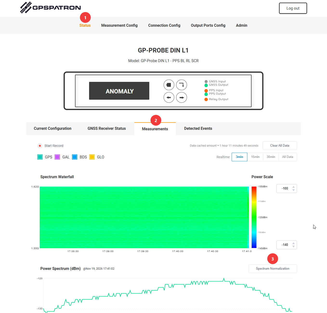
GP-Cloud: Open the probe's spectrum view and use the available spectrum calibration control. The same clean-spectrum requirement applies.
Step 1. Connect a suitable active GNSS antenna
Connect and power an active GNSS antenna. Its amplifier gain must be sufficient to overcome the losses of the RF cable and other passive components, so that the antenna's amplified noise is clearly stronger than the detector's own receiver noise.
How to check:
- Observe the background spectrum and peak power (dBm) with the antenna disconnected and the RF input terminated with a suitable 50 ohm load.
- Connect the active GNSS antenna and observe the spectrum again under interference-free conditions.
- The broadband background noise level should rise noticeably across the usable antenna frequency range. An increase of approximately 10 dB or more is a useful practical target.
A clear increase indicates that noise from the antenna path is contributing significantly to the measured spectrum. If there is little or no increase, the detector's internal noise may dominate and this calibration method may not be reliable. A noise increase is a practical indication, not a guarantee of absolute measurement accuracy.
Step 2. Make sure the spectrum is free of interference
Before starting calibration, watch the Power Spectrum for several minutes in the web panel or GP-Cloud. The background spectrum must be free of narrowband peaks, broadband jamming, or other abnormal signals. The spectrum does not have to be flat before calibration; its uneven shape is what the calibration is designed to correct.
Do not calibrate while interference is present. Otherwise, the calibration may treat the interference as part of the normal frequency response and distort subsequent power measurements.
Step 3. Click "Calibrate Spectrum"
1. Open the GP-Probe Web Configuration Panel. If you need help connecting to it, see How to Access the GP-Probe Configuration Panel.
2. Go to Status > Measurements.
3. Find the Power Spectrum graph, confirm that the spectrum is free of interference, and click Calibrate Spectrum next to the graph.
4. Check that the resulting background spectrum is approximately flat. On a multi-channel probe, repeat the procedure separately for each antenna channel.
Figure 1. Power Spectrum before calibration
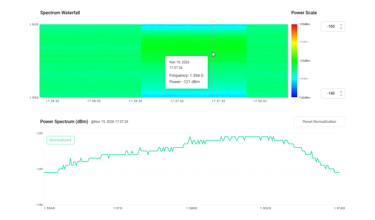
Figure 2. Power Spectrum after calibration
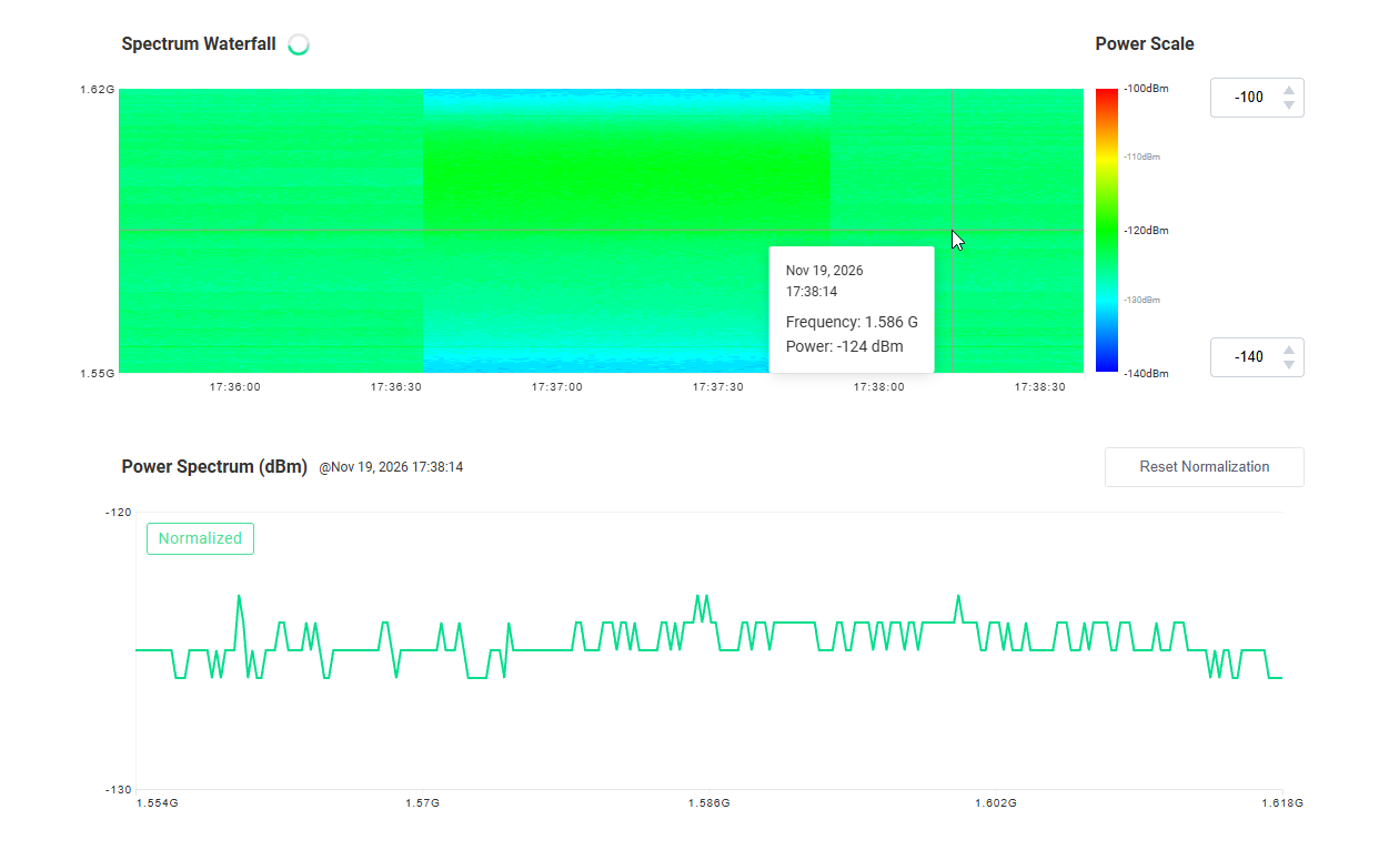
Both screenshots should show the same probe and antenna under comparable, interference-free conditions. Replace the two bracketed placeholders with images in the Freshdesk editor.
Step 4. Verify the result
The calibrated background noise spectrum should be approximately flat within the antenna's supported frequency range. Its average level should be close to -173 dBm/Hz (approximately -119 dBm per 250 kHz).
Note: The Peak Power indicator represents the strongest individual spectrum point. Because random noise fluctuates, Peak Power can be several decibels above the average. It is not the calibration target.
Repeat calibration whenever the antenna, RF cable, splitter, amplifier, or other relevant components are changed.
Technical Background
Why antenna gain and cable loss matter
Different antennas and cable runs produce different net RF gains. For example:
Parameter | Installation A | Installation B |
|---|---|---|
Active antenna gain | 40 dB | 30 dB |
Cable and passive losses | 10 dB | 20 dB |
Net RF gain | +30 dB | +10 dB |
Without compensation, the same interference signal arriving at the antenna could produce markedly different power levels at the detector input. Spectrum Calibration estimates a correction from the antenna's background noise, rather than requiring the complete RF gain budget.
Why use -173 dBm/Hz as the reference?
Thermal noise generated by a matched source at 290 K has a power spectral density of approximately -174 dBm/Hz. An active GNSS antenna also contains a low-noise amplifier (LNA), which adds its own noise. Many commercial active GNSS antennas have LNA noise figures around 2-3 dB, although some models are lower and others are higher.
For an engineering reference, GPSPATRON uses a 2.5 dB nominal LNA noise figure and an assumed effective antenna noise temperature of 130 K for an open-sky installation. The 130 K assumption depends on the antenna, its field of view, and the environment; it is not a universal value.
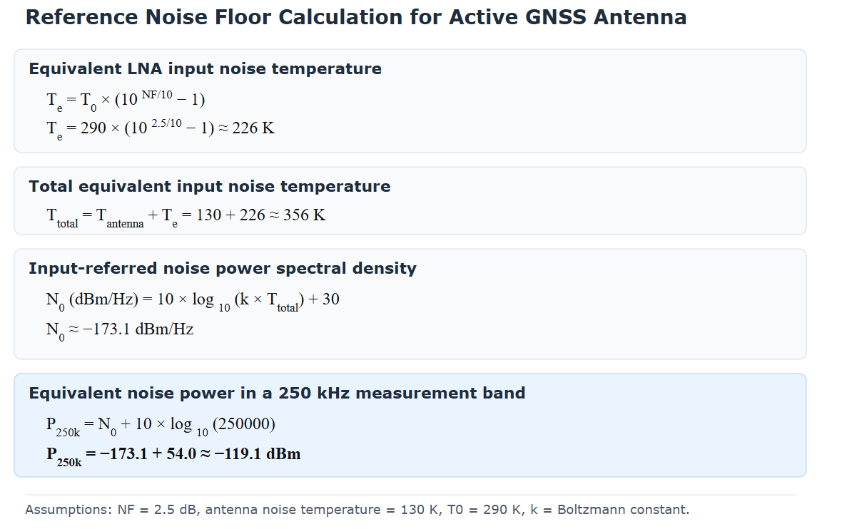
Here, k is the Boltzmann constant. The per-bin value assumes an effective noise bandwidth of 250 kHz. If the receiver uses another effective measurement bandwidth, its corresponding dBm-per-bin reference must be recalculated; the -173 dBm/Hz density reference remains the same.
How antenna noise enables normalization
When antenna-originated noise dominates the detector noise, both that noise and external RF interference pass through the same LNA, cable, and associated RF path. Their measured levels are therefore affected by approximately the same net gain. Using the antenna noise as a reference makes it possible to compensate for this unknown gain and express later measurements on a common, estimated input-referred scale.
Flattening is applied as a frequency-dependent correction to the background response. The intent is to remove the normal slope and ripple of the receiving path while preserving any new interference peaks that appear after calibration.
How much variation is expected between antennas?
Even with identical cable gains, different antennas may have different LNA noise figures. With the same assumed 130 K antenna noise temperature, the estimated reference varies as follows:
LNA Noise Figure | Estimated PSD | Per 250 kHz |
|---|---|---|
2.0 dB | -173.8 dBm/Hz | -119.9 dBm |
2.5 dB (reference) | -173.1 dBm/Hz | -119.1 dBm |
3.0 dB | -172.4 dBm/Hz | -118.4 dBm |
The selected value is a practical common reference, not a precise property of every active GNSS antenna.
Why calibration matters for interference heatmaps
A distributed monitoring network may contain detectors on rooftops, coastal sites, vessels, and industrial facilities. Without normalization, differences in antenna gain and cable attenuation can look like differences in interference intensity. A common noise reference reduces this bias and supports more meaningful comparisons between stations, changes over time, and estimated interference heatmaps.
Important Limitations
- Active antenna required: The technique relies on amplified antenna noise dominating the detector's internal noise. It is not appropriate for a passive antenna or a disconnected/attenuated RF input without a suitable dominating noise source.
- No interference during calibration: Jamming or other RF signals can corrupt the reference spectrum.
- Estimated, not traceable: Real antenna noise figure and antenna noise temperature differ by model and installation. The -173 dBm/Hz reference is an engineering approximation.
- Frequency range matters: The method applies only within frequency regions sufficiently supported by the antenna and receiving path; deep antenna/filter rejection regions cannot be recovered by numerical flattening.
- Radiation patterns are not corrected: Different antenna patterns and polarization responses can cause different received interference levels, particularly for sources near the horizon. This method does not estimate absolute incident field strength.
- Receiver linearity matters: Automatic gain changes must be handled correctly, and strong signals causing compression or saturation can invalidate the power estimate.
Summary
Calibrate Spectrum removes normal frequency-response unevenness and brings the average noise floor to a common estimated reference of -173 dBm/Hz (approximately -119 dBm per 250 kHz). With a correctly powered active GNSS antenna, adequate gain over cable losses, and an interference-free reference spectrum, this provides a practical way to compare interference power across GP-Probe DIN L1 and TGE2 installations.