
This Quick Start guide provides an overview of available GP-Jammer Bundles, their contents, and initial setup steps.
The guide is intended for engineers and researchers performing RF interference resistance testing, and experiments in laboratory environments.
1. Overview of Available Bundles
GP-Jammer is available in two predefined bundle configurations. Each bundle is delivered as a ready-to-use portable test kit.
1.1 GP-Jammer Bundle – 3-Channel Kit
SKU: GPJ/BUNDLE/3CH
Compact multi-band GNSS jamming test kit focused on L1/L2/L5 receiver testing and interference scenario generation. Includes software, SDRs, laptop, and RF accessories — all packaged in a rugged portable case.
Included components:
- GP-Jammer 3-Channels Perpetual License (1 PC)
- GP-Jammer RFSG Kit – 3× Pluto SDR with combiner, attenuators, and RF cables (1 pc)
- Laptop (1 pc)
- Rugged transport case (1 pc)
1.2 GP-Jammer Bundle – 16 Channels / 1W
SKU: GPJ/BUNDLE/16CH/1W/19R
Turnkey solution for advanced CRPA antenna testing, spatially distributed interference generation, and over-the-air vulnerability evaluation. Fully equipped for immediate deployment.
Included components:
- GP-Jammer Unlimited License (with Automation Script and API Control options)
- 16 × GP-Jammer SDR – 9361, installed in GP-Jammer RackFrame Adapter
- 16 × GP-Jammer AMP – 1 Watt, installed in GP-Jammer RackFrame Adapter
- Laptop (1 pc)
- Rugged transport case (1 pc)
2. Package Layout (GP-Jammer Bundle – 3-Channel Kit)
Below is an example of how the GP-Jammer Bundle is supplied in the rugged transport case.
Typical layout:
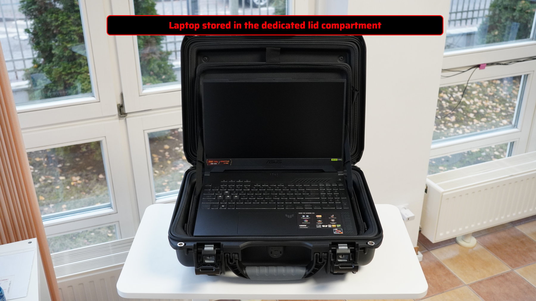
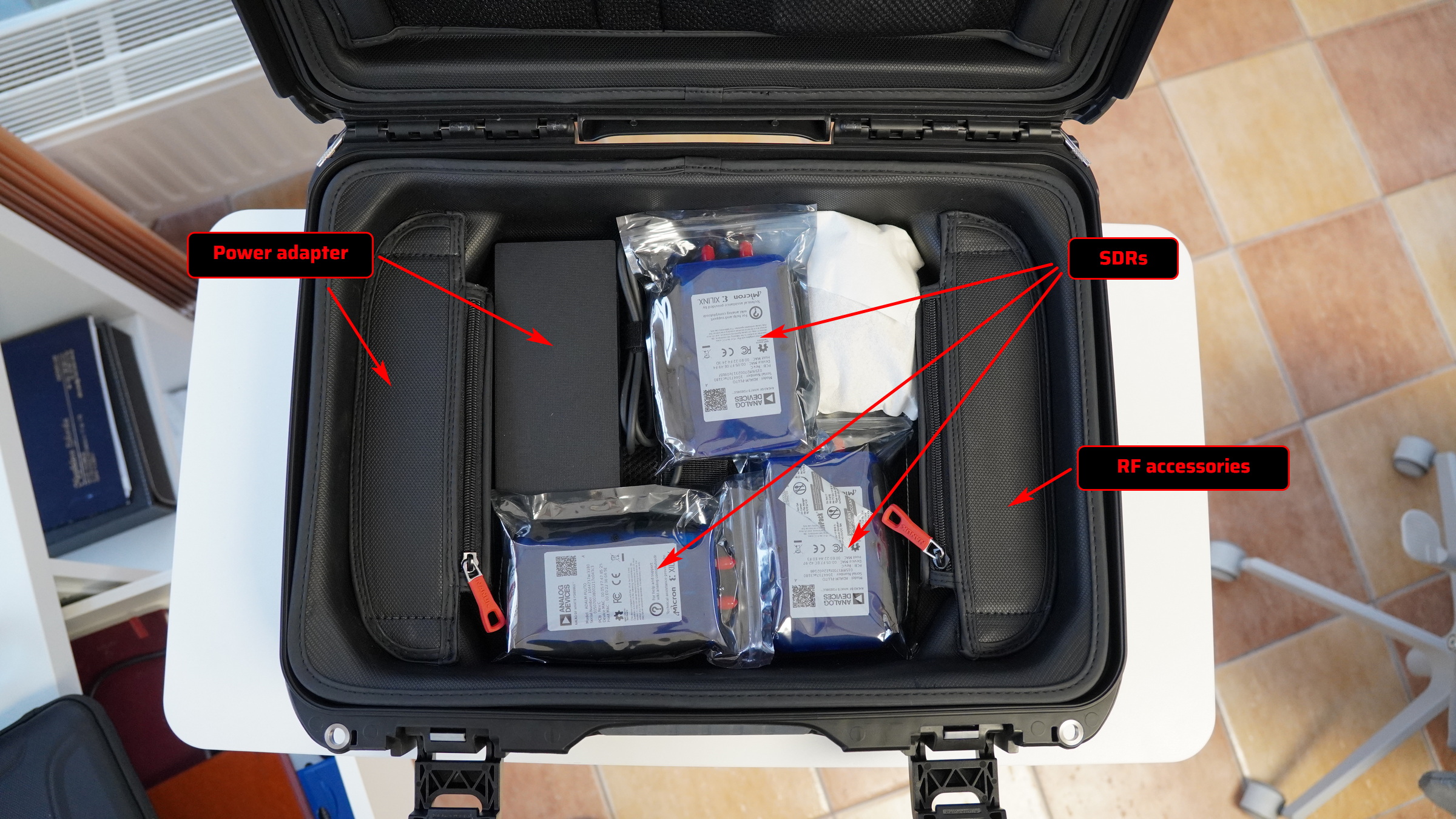
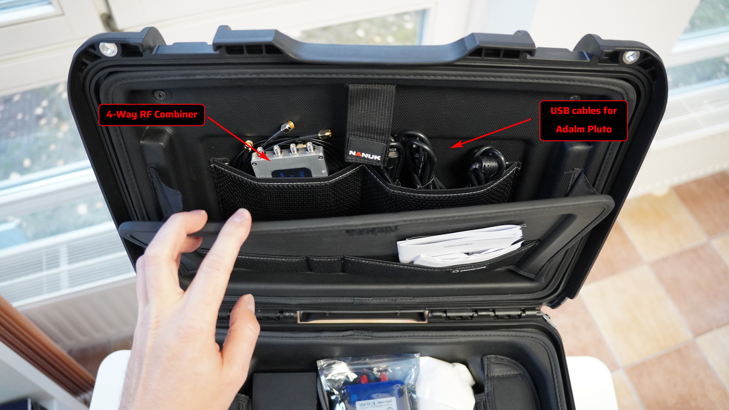
⚠️ Actual layout may vary slightly depending on regional configuration, but all RF paths and accessories are clearly labeled.
3. Connecting Hardware
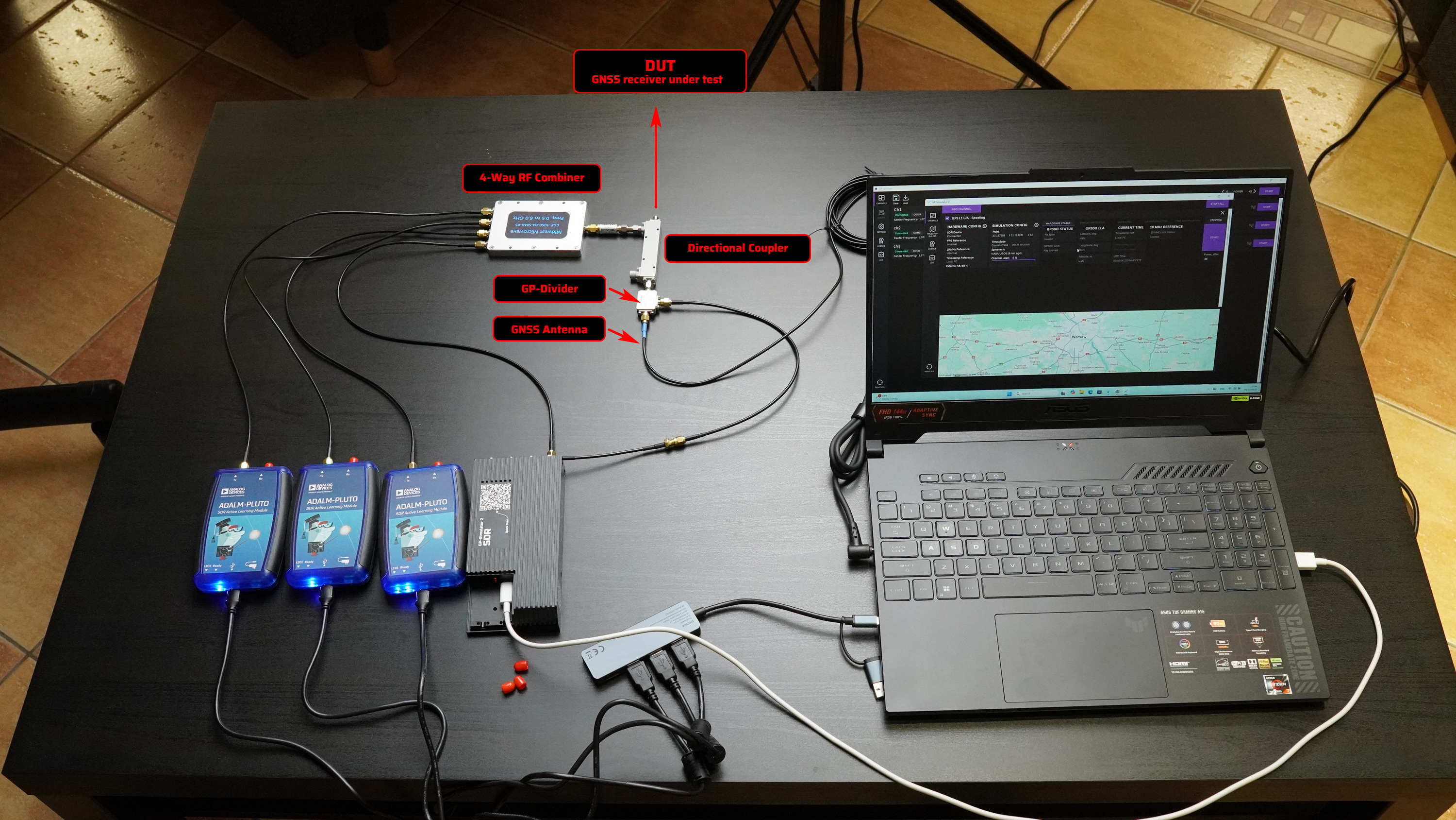
Advanced GNSS receiver test with GP-Jammer and GP-Simultor (is not included in the Jammer Bundle delivery kit)
This section describes the basic RF interconnection required to test a GNSS receiver under simultaneous spoofing and jamming conditions.
3.1 SDR and Computer Connections
The setup uses four SDR devices connected to a single control computer:
- Three Adalm-Pluto SDRs
These SDRs are used for jamming signal generation.
All Adalm-Pluto units are connected to the computer via a USB hub, allowing multiple SDRs to operate simultaneously. - One GP-Simulator 2 SDR (is not included in the Jammer Bundle delivery kit)
This SDR is used for GNSS signal simulation. It is connected directly to the computer via USB, without a hub, to ensure maximum stability and throughput.
The computer runs both GP-Simulator 2 and GP-Jammer software and controls all connected SDR devices.
3.2 RF Signal Combining
The TX outputs of all four SDRs are connected to the inputs of a 4-Way RF Combiner.
The RF combiner merges:
- GNSS simulated signal from the GP-Simulator 2 SDR
- Jamming signals from the three Adalm-Pluto SDRs
At the output of the RF combiner, a single composite RF signal is formed.
3.3 Attenuator and Directional Coupler
The combined RF signal is routed through an optional 10 dB attenuator. This attenuator is used to reduce signal level and protect the DUT input. After the attenuator, the signal is injected into one arm of a directional coupler. The arm used is the one closest to the main output that goes toward the DUT.
This configuration ensures correct signal injection with predefined power level attenuation (10 dB).
3.4 DUT Connection
The main output of the directional coupler is connected directly to the RF input of the DUT (GNSS receiver under test).
The DUT receives:
- Live GNSS signals from the antenna
- Injected spoofing signals
- Injected jamming signals
This creates realistic test conditions for combined GNSS threats.
3.5 GNSS Antenna Connection
A GNSS antenna is connected to the input port of the directional coupler via a GP-Divider. The GNSS antenna can be:
- The antenna supplied with the kit, or
- Any compatible active GNSS antenna.
Antenna Power
Antenna bias voltage must be supplied by the DUT. No external antenna power source is required.
Purpose of the GP-Divider
The GP-Divider allows a single GNSS antenna to be used simultaneously for:
- The DUT
- The SDR GPSDO input (used for timing and synchronization for coherent spoofing testing)
This eliminates of the need for a second antenna
4. Next Steps
After completing the hardware setup, proceed with: