TABLE OF CONTENTS
Overview
GP-Simulator 2 provides two operational modes for generating a navigation signal:
- Simulation mode
- Spoofing mode
The simulation mode generates a standard GPS signal for receiver testing.
In the simulation mode, user can adjust the following settings:
- Select a static point.
- Specify the time of the generation.
- Define a dynamic trajectory.
- Control the output power.
- Adjust per-satellite signal strength during runtime.
The spoofing mode include both coherent and non-coherent spoofing. The spoofing mode allows real-time manipulation of position and timing parameters during signal generation. It helps evaluate receiver resilience to spoofing.
In the spoofing mode, user can use the following feature:
- Manual LLA (latitude, longitude, altitude) override.
- Instant position jumps or gradual movement.
- Dynamic spoofed motion using trajectory simulation.
To start using GP-Simulator 2, follow the steps:
1. Connect SDR and update drivers
Refer to the Hardware installation guide for details.
2. Install software and activate licence
Refer to the Software installation guide for details.
3. Start generation in the simulation or spoofing mode.
Simulation Mode
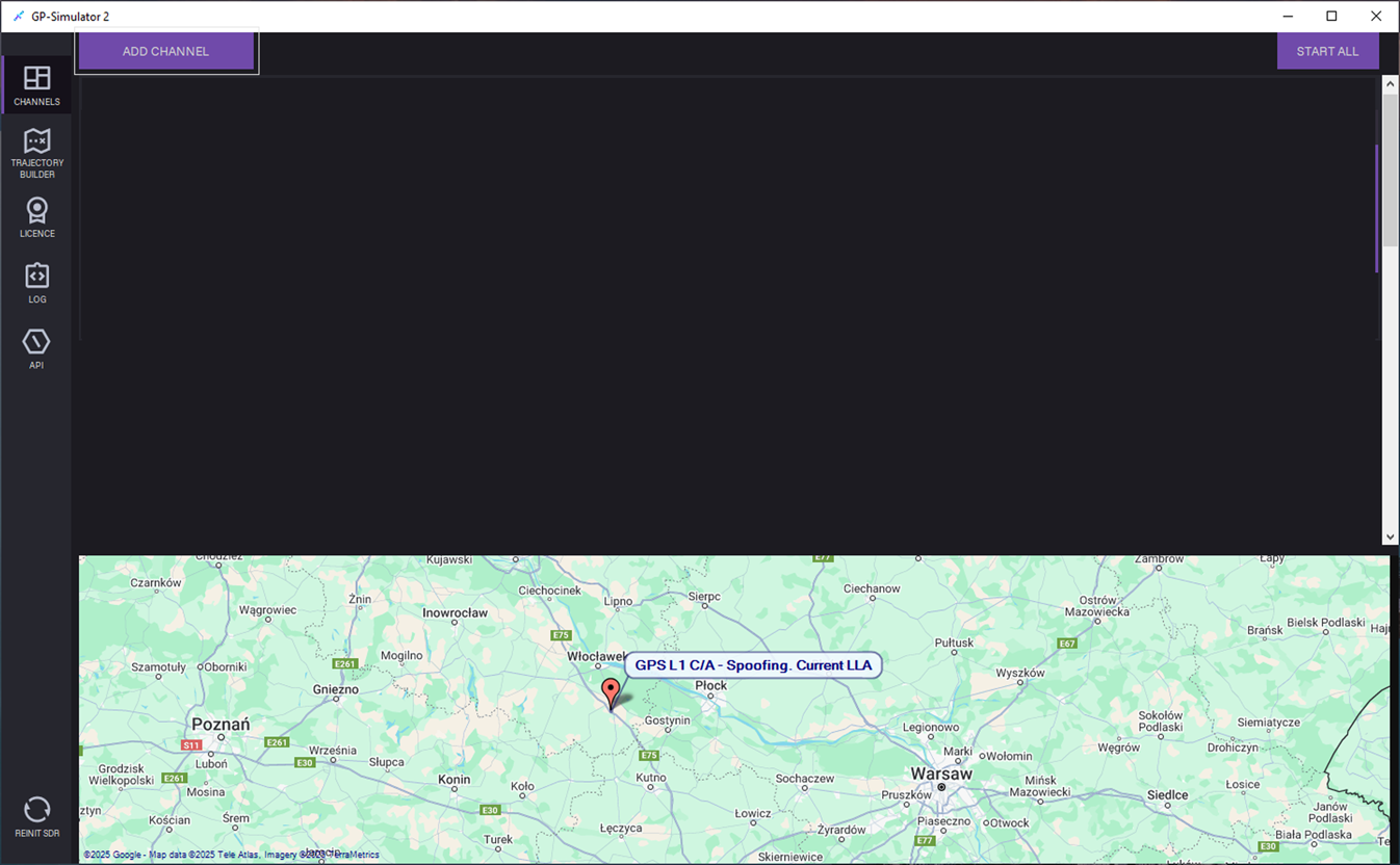
1.Open the CHANNELS tab and click ADD CHANNEL.
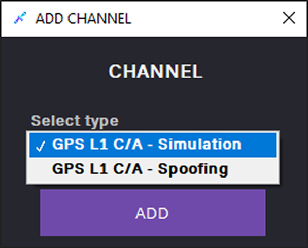
2. In the ADD CHANNEL dialog, select the GPS L1 C/A – Simulation channel and click ADD.

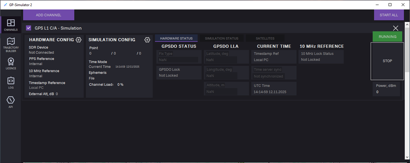
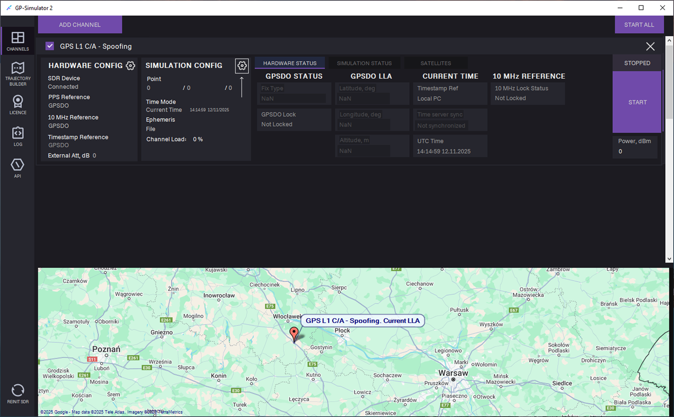
3. The channel is added to the CHANNELS tab.
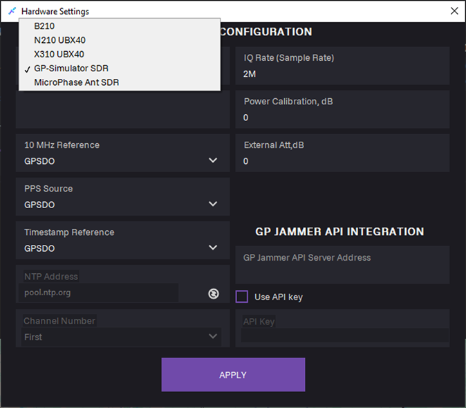
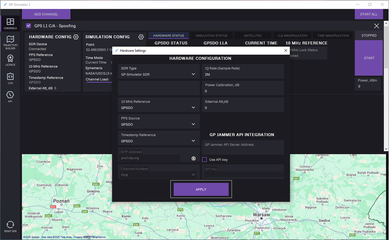
 4. Adjust HARDWARE CONFIG: Click the Settings
 icon. Hardware settings dialog opens.

5. In the SDR type field, select SDR from the list.
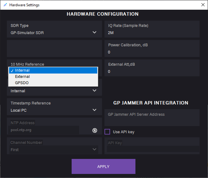
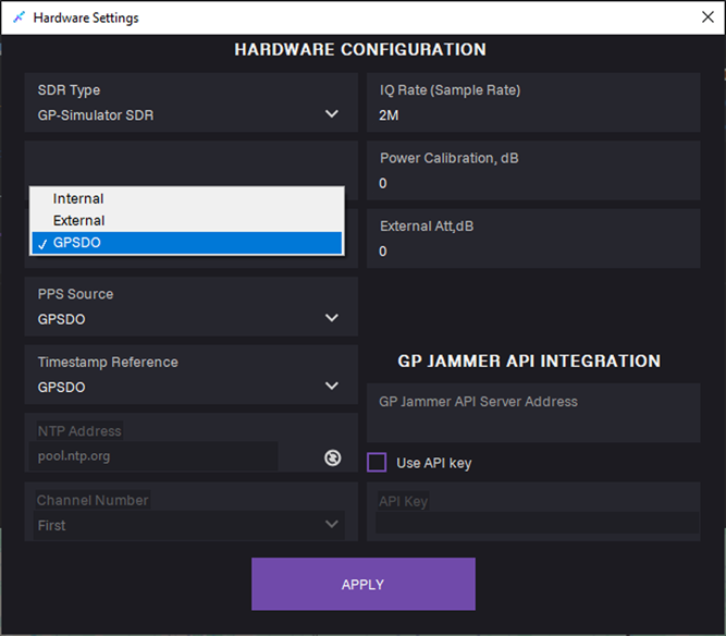
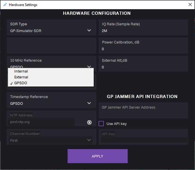
6. In the 10 MHz Reference field, select clock source:
- Internal
- External: Use for external 10 MHz reference.
- GPSDO: Use for disciplined onboard oscillator.
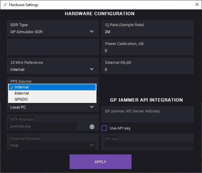
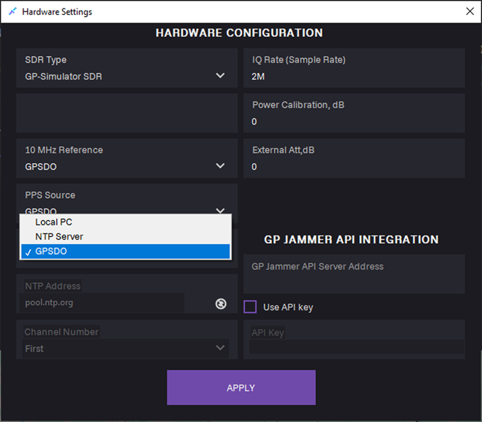
7. In the PPS Source field, select pulse-per-second synchronization input:
- Internal
- External
- GPSDO
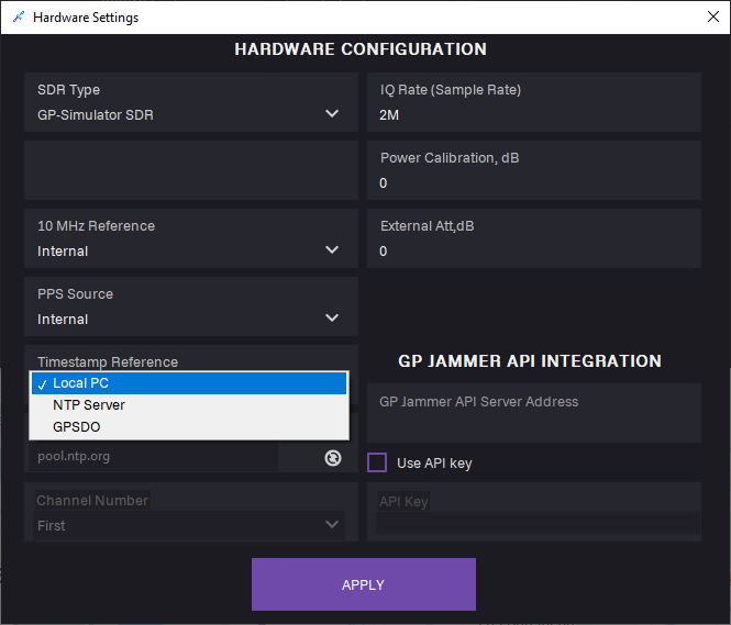
8. In the Timestamp Reference field, select time base for GPS data alignment:
- Local PC
- NTP Sever
- GPSDO

9. Click APPLY.

10. Adjust SIMULATION CONFIG: Click the Settings icon.
icon.
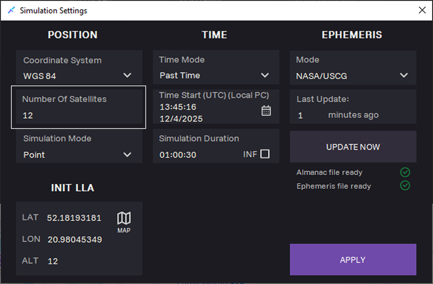
11. Optional: In the Number of Satellites field, select maximum number of satellites. The actual number of satellites will be defined by the ephemeris data.

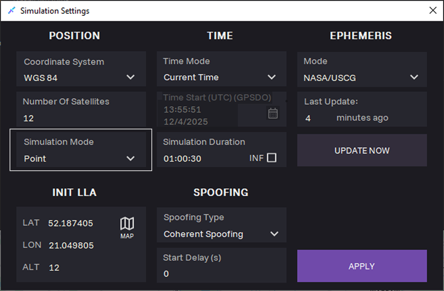
12. Select position simulation mode:
- Point: Use for fixed location scenario.
- Trajectory: Use for dynamic scenario moving the simulated receiver along the selected path
Point mode
When selecting the Point mode, the INIT LLA section appears for selecting coordinates. Define the coordinates manually or from map.
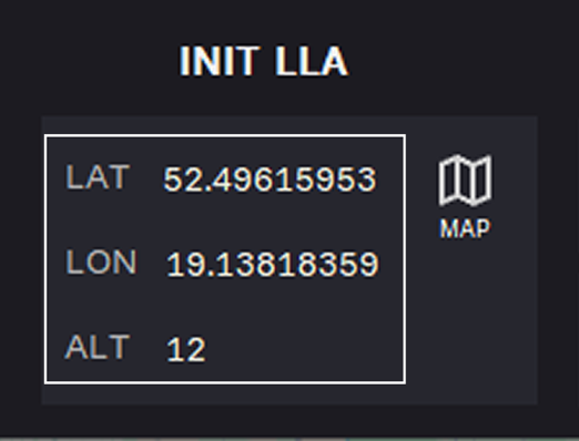
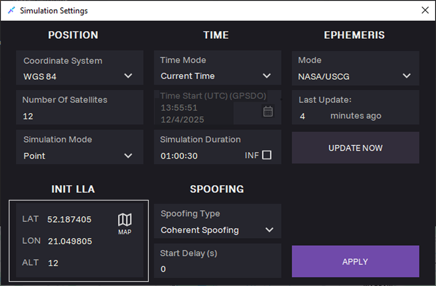
13. Select coordinates.
Option 1. Enter coordinates manually:
- LAT — latitude
- LON — longitude
- ALT — altitude
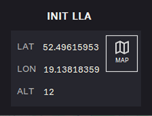
Option 2. Select coordinates from map: Click the MAP symbol.
Select coordinates from map
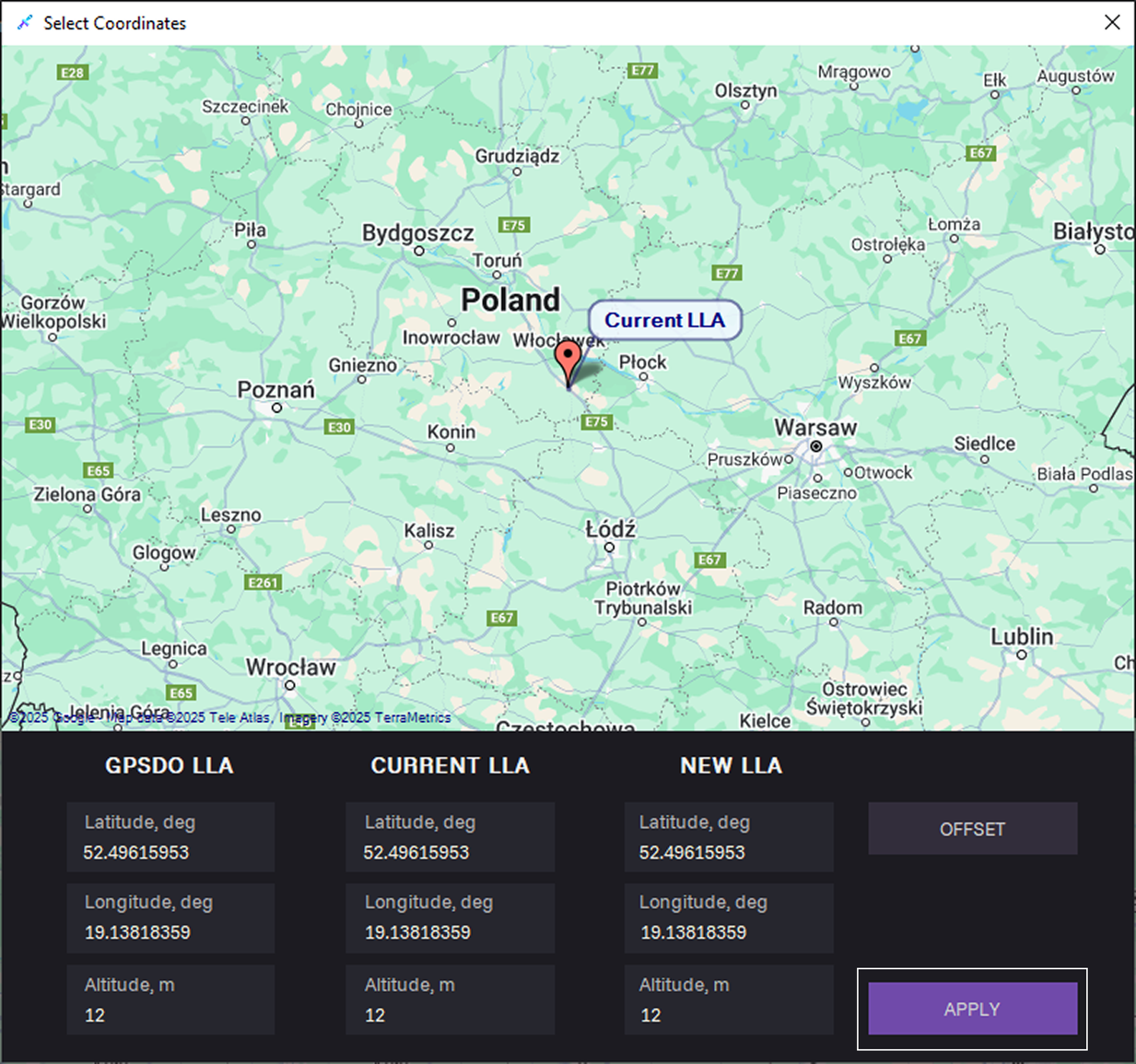
In the Select Coordinates dialog, define the coordinates in one of the following ways:
- Place a point on the map and click Apply.
- Click OFFSET to describes a position relative to reference point.
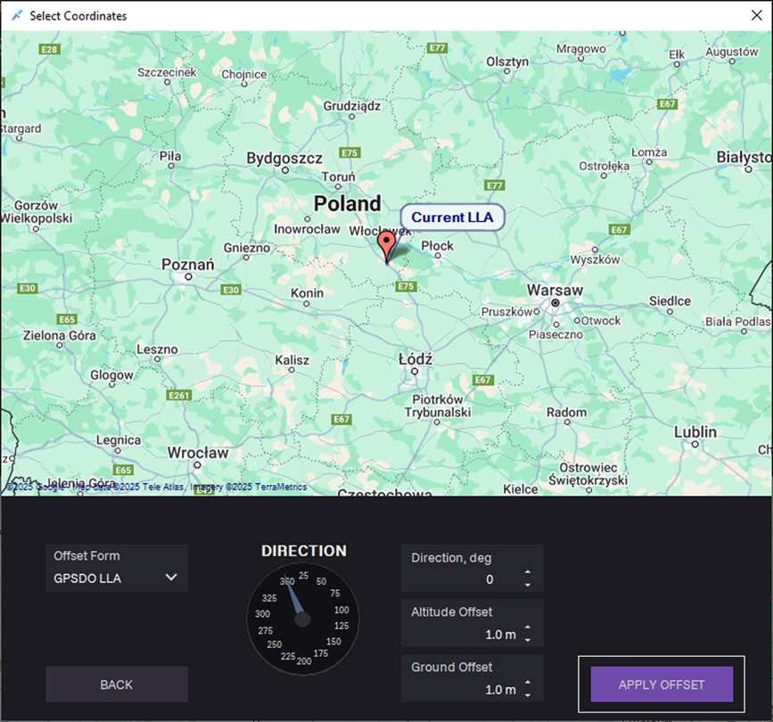
To describe a position relative to a reference point, perform the following steps:
a. In the Offset Form field, select a reference point:
- GPSDO LLA
- Current LLA
b. Choose direction:
- Enter Direction, deg — compass heading measured clockwise.
- Fill in the Altitude Offset in meters – vertical distance relative to the reference point.
- Fill in the Ground offset in meters – horizontal distance relative to the reference point.
c. Click APPLY OFFSET.
Trajectory mode
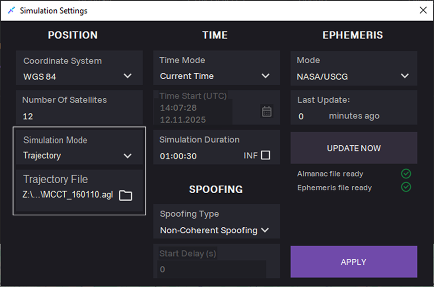
14. When selecting Trajectory simulation mode, upload a file describing the object's trajectory in TRJ format in the Trajectory File field. To obtain a file with a simulated trajectory, go to the TRAJECTORY BUILDER tab.
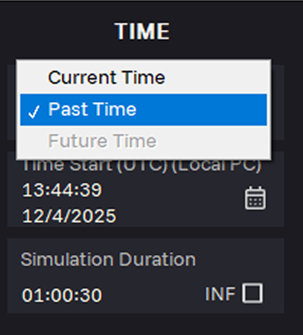
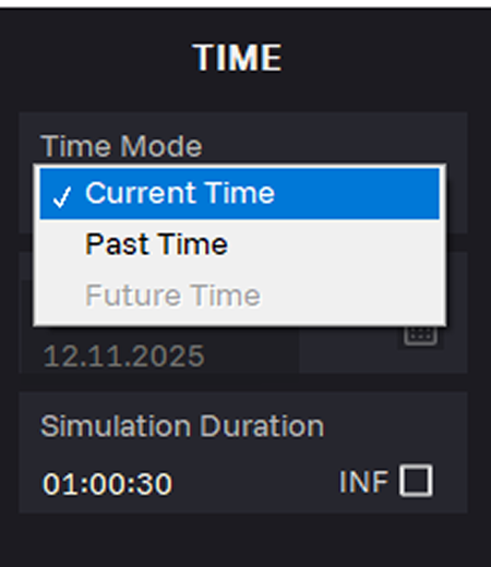
15. In the Time Mode field, select the Past time period. Simulation reproduces historic satellites configuration and timing conditions.
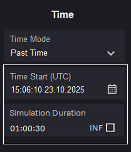
16. Select the simulation start date and time in UTC in the Time Start (UTC) field. After each change to the Time Mode and Time Start (UTC) parameters, you must download the latest almanac and ephemeris files.
17. Enter time in the Simulation Duration field. Select the INF check box, to upload new ephemeris automatically.
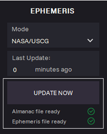
18. Click UPDATE NOW to download actual data for the selected simulation Time Start (UTC).
Last Update: Time of the last update almanac and ephemeris data.

19. Click APPLY.

20. Click START to start generation.
21. To stop generation, click STOP.
Spoofing Mode
Coherent Spoofing
Coherent (synchronous) spoofing generates a synthetic navigation field corresponding to a predefined simulation point. The approach utilizes current almanac and ephemeris data and synchronizes the signal generation start with the reception of an authentic navigation frame, allowing two generation start opportunities per minute with a 30-second interval.
To start coherent spoofing, follow the steps below.
1. Make sure the GPS antenna is mounted on the ANT connector.

2. Open the CHANNELS tab and click ADD CHANNEL.
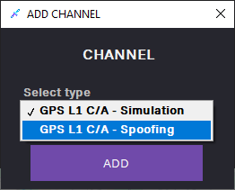
3. In the ADD CHANNEL dialog, select the GPS L1 C/A – Spoofing channel and click ADD.

4. The channel is added to the CHANNELS tab.
 5. Adjust HARDWARE CONFIG: Click the Settings
 icon. Hardware settings dialog opens.
6. In the SDR type field, select SDR from the list.
7. In the 10 MHz Reference field, select the GPSDO clock source.
8. In the PPS Source field, select the GPSDO pulse-per-second synchronization input.
9. In the Timestamp Reference field, select the GPSDO time base for GPS data alignment.
10. Click APPLY.
11. Adjust SIMULATION CONFIG: Click the Settings icon.
icon.

12. Optional: In the Number of Satellites field, select maximum number of satellites.
The actual number of satellites will be defined by the ephemeris data.
13. Select the Point simulation mode.
14. Enter coordinates in the INIT LLA section:
- LAT — latitude
- LON — longitude
- ALT — altitude
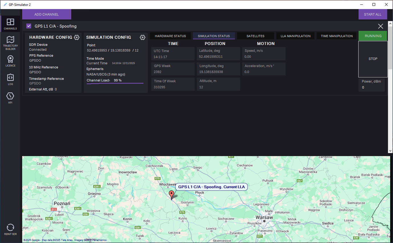
15. In the Time Mode field, select Current Time. Simulate GNSS signal based on the real-time system clock.
16. Enter time in the Simulation Duration field. Select the INF check box, to upload new ephemeris automatically.
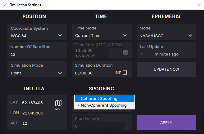
17. When selecting Current Time generation, SPOOFING section appears. Select Coherent (synchronous) spoofing type.
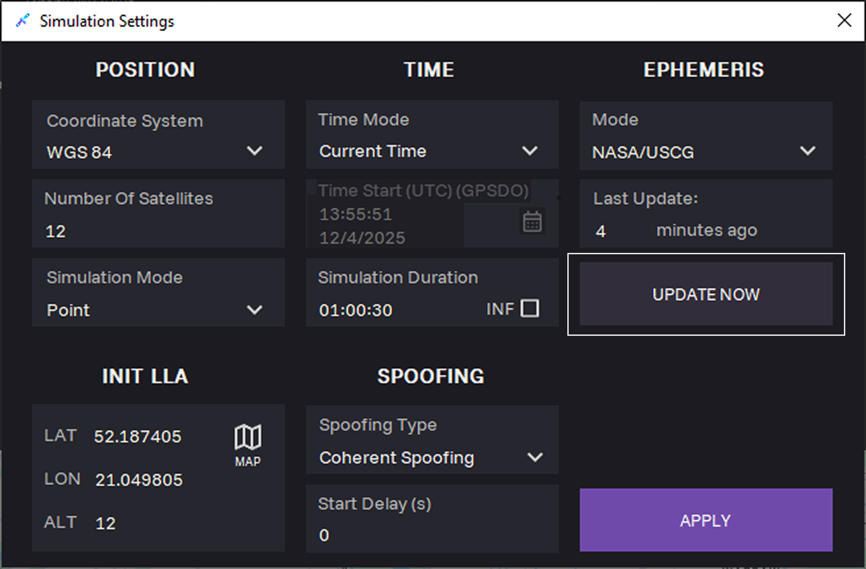
18. Click UPDATE NOW to upload the latest almanac and ephemeris files.
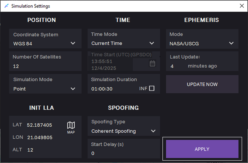
19. Click APPLY.

20. Click START to start generation.
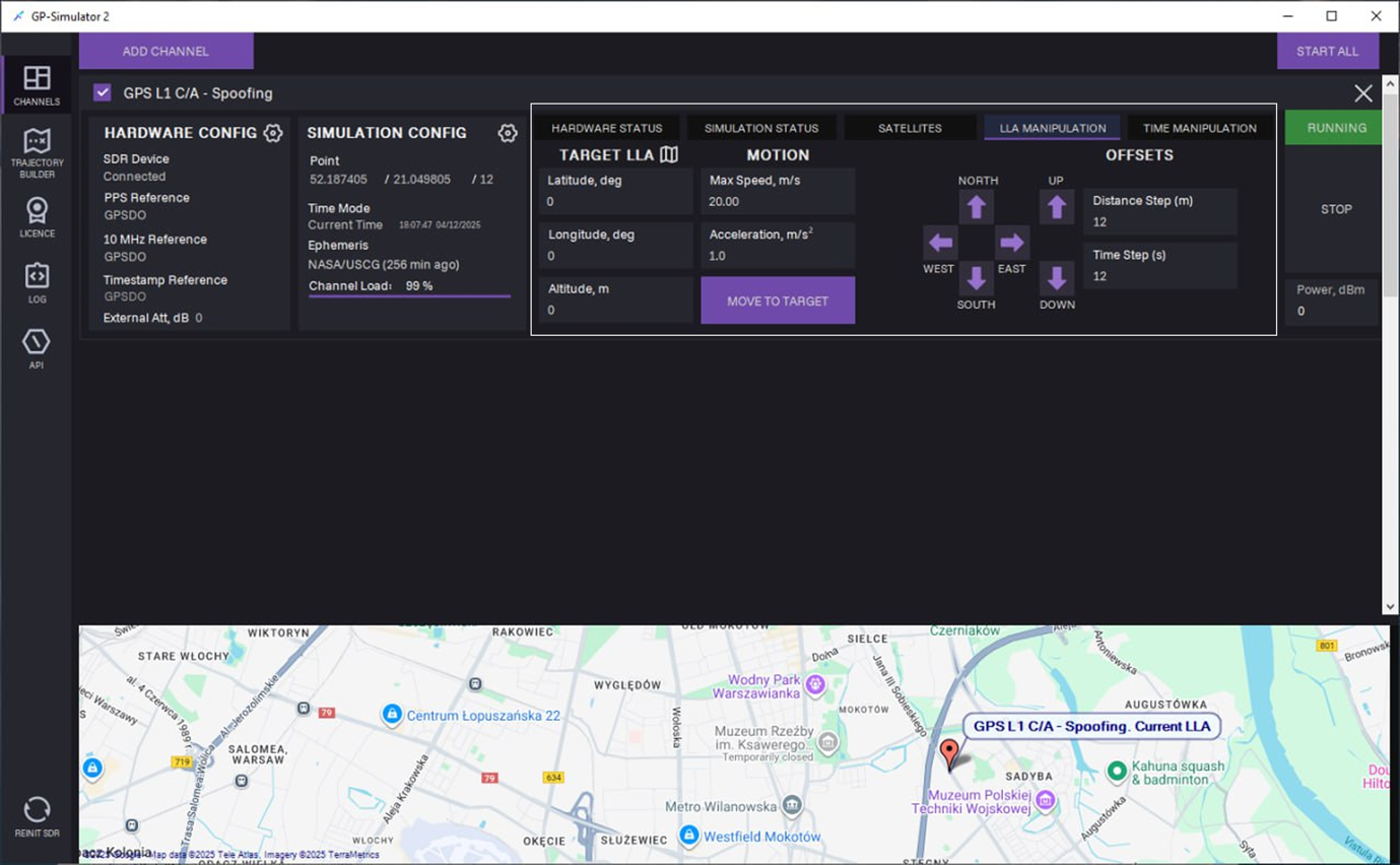
21. On the LLA MANIPULATION tab, target LLA manipulation can be performed during signal generation in one of the following ways:
- Manually
- Offsets
- From map
Manually
a. Enter coordinates in the following fields:
- Latitude, deg
- Longitude, deg
- Altitude, m
b. Enter Max Speed, m/s and Acceleration m/s2.
c. Click MOVE TO TARGET.
Offsets
a. Select direction using arrows:
- North
- West
- South
- East
- Up
- Down
b. Enter Distance Step (m) and Time Step (s).
c. Click MOVE TO TARGET.
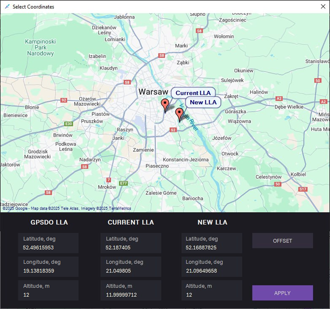
From map
a. Click on the map symbol.
b. Select New LLA on the map and click APPLY.
c. Enter Max Speed, m/s and Acceleration m/s2.
c. Click MOVE TO TARGET.
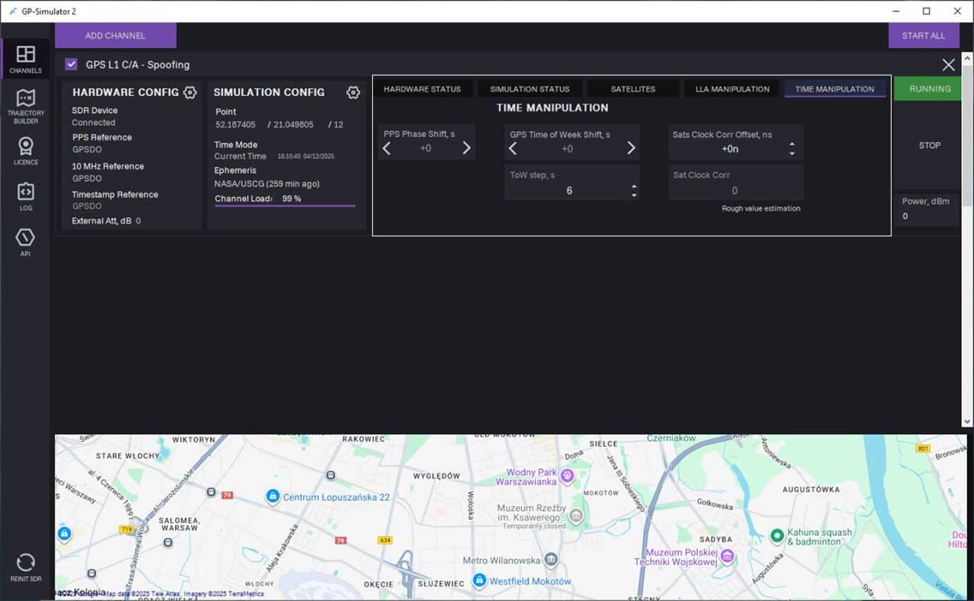
22. On the TIME MANIPULATION tab, the following manipulation can be performed during signal generation:
- PPS phase shift
- Time of the week offset
- Satellite clock bias simulation
23. To stop generation, click STOP.
Non-Coherent Spoofing
Non-coherent spoofing mode functions similarly to coherent mode but does not require phase synchronisation between the GPS signal and the receiver.
For non-coherent mode, you can select the following parameters:
1. Select any 10 MHz Reference source:
- Internal
- External
- GPSDO
2. Select any PPS source:
- Internal
- External
- GPSDO
3. Select any Timestamp Reference source:
- Local PC
- NTP Sever
- GPSDO
4. In the Time Mode field, select Current Time.
5. In the SPOOFING section, select Non-Coherent Spoofing type.
The rest steps are the same as in coherent spoofing mode.
Multi-Channel Signal Generation 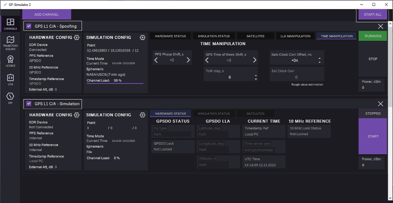
To start multi-channel generation (Optional), follow the steps:
- Add one more channel: Click ADD CHANNEL, select channel type, and click ADD.
- Make sure the Channels checkboxes are selected.
- Click START ALL.
Multi-channel generation is started.
Trajectory Builder
Trajectory builder is build-in graphical editor for creating and editing movement paths.
 To create a trajectory file, follow the steps:
- To create the first point, double-click on the desired location on the map. Point coordinates are added to the table.
- Continue creating the path by double-clicking on the map.
- To edit point coordinates, click on the relevant table cell and adjust value.
- Optional: Assign speed and acceleration per segment.
- Click SAVE AS to save the path to the PC.
Select this file in the simulation settings for Trajectory simulation mode.
LOG Tab
The LOG tab is used for storing, viewing and analysing event journals that record the operation of the generator, the app, and interaction with APIs. It contains the following sections:
- Generation Log — a system event journal that retains information about the processes and operations related to generation.
- System Log — a system event journal that records the internal activity of the application.
- API Log — a system event journal that stores logs of interactions with external APIs.
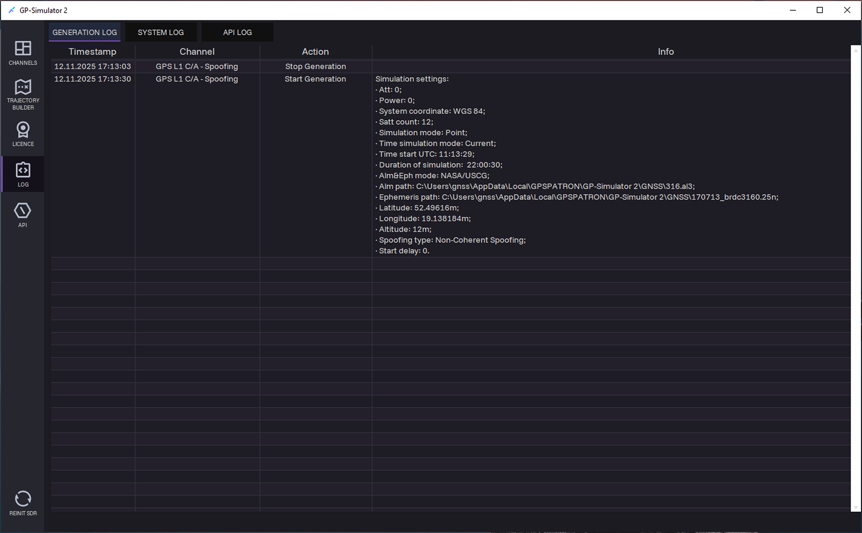
Generation log
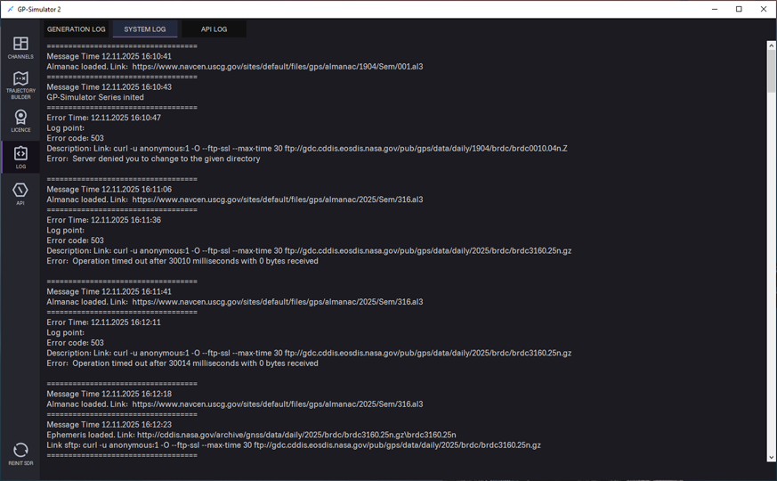
System log
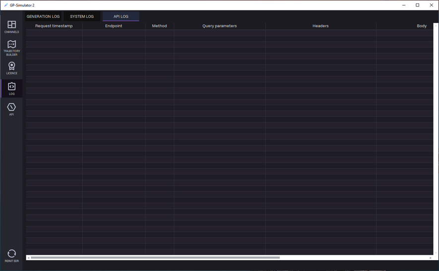
API log